

Efficient and energy-saving ice maker
A high-efficiency, energy-saving, ice-dispensing machine technology, which is applied in the fields of ice manufacturing, ice storage/distribution, lighting and heating equipment, etc., can solve the problems of unsecured safety, unreasonable structure, and low work efficiency, so as to save labor costs , Reasonable structure, fast delivery of ice
- Summary
- Abstract
- Description
- Claims
- Application Information
AI Technical Summary
Problems solved by technology
Method used
Image


Examples
Embodiment 1
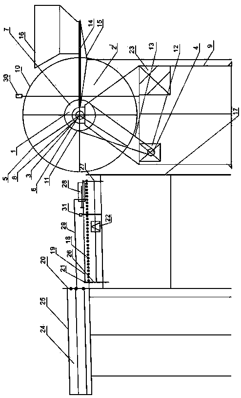
[0031] Such as figure 1 As shown, a high-efficiency energy-saving ice machine according to the present invention includes a main bracket 9, a spindle tube 1, an ice guiding blade 14, an ice guiding blade side block 16, and a first probe 30. The main bracket 9 is provided with There are ice guide gear motor 12, control system 23 and first probe 30, the upper end of main bracket 9 is provided with circular side ice block 10, the main shaft round tube 1 is arranged at the center of circular side ice block 10, the main shaft round tube 1 two Bearing 3 and bearing seat 8 are provided at the end and are supported by main bracket 9, and are driven and rotated by deceleration motor 12 of ice guide machine. Three crampons 2 are arranged on the same axis on the main shaft circular tube 1, and the circular side ice blocks 10 Evenly divided into multiple sectors. The crampons 2 are V-shaped, and the angle between adjacent crampons 2 is 90°≤α<120°. The ice guide slider 14 is horizontally...
Embodiment 2
[0036] Such as figure 2 As shown, in this embodiment, except that the number of crampons 2' set on the same axis on the main shaft tube 1 is four, the shape of the crampons 2' is no longer V-shaped, but narrow and convex, and the adjacent crampons The angle β between 2' is 90°, and the position between adjacent crampons 2' just ensures that an ice cube slides therebetween without falling down. The remaining parts are completely consistent with Embodiment 1 and will not be repeated here.
PUM
 Abstract
Description
Claims
Application Information