Directional rod conveying device for copper rod rolling mill

A copper rod and rolling mill technology, applied in metal rolling, metal rolling, manufacturing tools, etc., can solve the problems of copper rod winding in one body and reduce the working efficiency of copper rod rolling mill, so as to ensure the product appearance and quality, and simple structure , the effect of improving work efficiency

Inactive Publication Date: 2018-09-21
德阳市德东电工机械制造有限公司
View PDF0 Cites 0 Cited by
  • Summary
  • Abstract
  • Description
  • Claims
  • Application Information

AI Technical Summary

Problems solved by technology

[0004] The purpose of the present invention is to provide a directional feeding rod for copper rod rolling mill to solve the problem that the copper rod is easy to wrap itself and reduce the working efficiency of the copper rod rolling mill during the process of pulling the copper rod in the copper rod rolling mill. device

Method used


Image

  • Directional rod conveying device for copper rod rolling mill
  • Directional rod conveying device for copper rod rolling mill
  • Directional rod conveying device for copper rod rolling mill

Examples


Embodiment 1

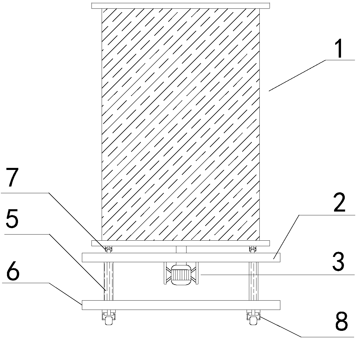
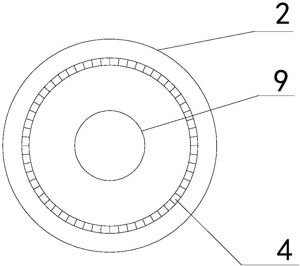
[0024] A directional rod feeding device for a copper rod rolling mill, comprising a bearing base 2, a through hole 9 is opened in the middle of the bearing base 2, a driving motor 3 is fixed on the bottom of the bearing base 2 through a mounting plate, the mounting plate and the bearing base 2 and The drive motors 3 are fixedly connected by screws. The output shaft of the driving motor 3 passes through the through hole 9 and is connected with the barrel 1 for winding the copper rod.

[0025] The working principle is as follows: before starting the copper rod rolling mill, the copper rod is wound on the barrel 1 from bottom to top, and after the winding is completed, the head of the copper rod is brought into the rolling mill. Turn on the copper rod rolling mill, and start the drive motor 3 at the same time, the drive motor 3 rotates, and drives the cylinder 1 connected to it to rotate, so that the copper rod wound on the cylinder 1 is separated from the cylinder 1 . The devic...

Embodiment 2

[0027] On the basis of Embodiment 1, swivel casters 7 are provided at the bottom of the cylinder body 1 , and slide rails 4 matched with the swivel casters 7 are provided on the bearing seat 2 . During the rotation process of the cylinder body 1 driven by the drive motor 3 , the swivel casters 7 at the bottom of the cylinder body 1 move on the slide rail 4 . Through this operation, the driving force required by the driving motor 3 to drive the barrel 1 is reduced, thereby reducing the consumption of material resources and improving the working efficiency of the entire device.

Embodiment 3

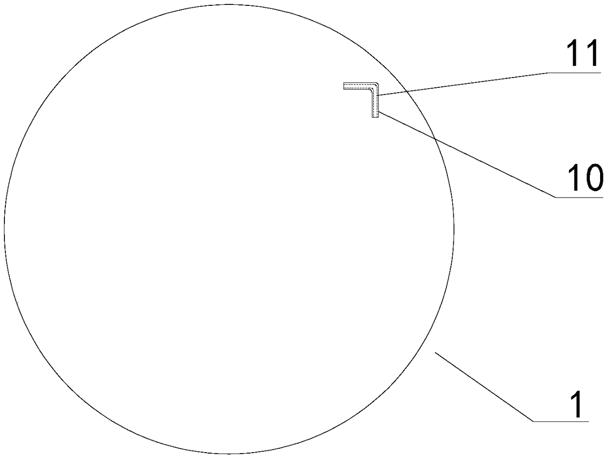
[0029] On the basis of any of the above-mentioned embodiments, the lower side of the bearing seat 2 is also provided with a lifting mechanism 10. The lifting mechanism 10 includes a cylinder 5 and a base 6 for carrying the cylinder 5. One end of the cylinder 5 is connected with the bearing seat 2, and the cylinder 5 The other end of the cylinder is connected with the base 6, and the connection modes between the cylinder 5 and the bearing seat 2 and the base 6 are all connected by screws. When the copper rod wound on the upper half of the cylinder 1 is separated from the cylinder 1, the cylinder 5 pushes the internal piston rod to move outward, so that the bearing seat and the components arranged on the bearing seat move upward together. This operation facilitates the delivery of copper rods to the copper rod rolling mill, thereby improving the working efficiency of the device.


PUM


Abstract

The invention discloses a directional rod conveying device for a copper rod rolling mill, and belongs to the field of mechanical equipment. The directional rod conveying device comprises a bearing seat. A barrel and a driving motor are arranged on the bearing seat, the barrel is used for winding copper rods, the driving motor is used for driving the barrel to rotate, a through hole is formed in the bearing seat, and an output shaft of the driving motor penetrates the through hole to be fixedly connected with the barrel. Rotary casters are arranged at the bottom of the barrel, and a slide railwhich is matched with the rotary casters is arranged on the bearing seat. Lifting mechanisms are further arranged on the lower side of the bearing seat and comprise air cylinders and bases, the basesare used for bearing the air cylinders, one end of each air cylinder is fixedly connected with the bearing seat, and the other end of each air cylinder is fixedly connected with the corresponding base. The directional rod conveying device has the advantages that the problem of low work efficiency of an existing copper rod rolling mill due to the fact that an existing copper rod needs to pulled bythe existing copper rod rolling mill and can be easily integrally wound around the copper rod can be solved by the aid of the directional rod conveying device, and the problem of influence on the conditions and the quality of products due to rubbing between the surfaces of existing copper rods which are in contact with one another in copper rod pulling procedures can be solved by the aid of the directional rod conveying device; the directional rod conveying device is simple in structure and high in work efficiency.

Description

technical field [0001] The invention belongs to the field of mechanical equipment, and in particular relates to a directional rod feeding device for a copper rod rolling mill. Background technique [0002] Copper rod rolling mill is a kind of equipment for rolling copper rod from large cross-section to small cross-section, which is mainly composed of rolling mill unit and gear box. Before the copper rod enters the rolling mill, most of the copper rods are directly placed on the side of the rolling mill. During the production process of the copper rod, the copper rod is pulled by the rolling mill for further operation. [0003] The mode of pulling the copper rod by the rolling mill to move has the following disadvantages: the one is that the rolling mill needs to disperse power to pull the copper rod, which leads to a reduction in the working efficiency of the rolling mill. The 2nd, in the process that rolling mill pulls copper rod, copper rod is easy to self-wound in one, c...

Claims


Application Information

Patent Timeline
IPC IPC(8): B21B39/02B21B1/16B21B15/00
CPCB21B39/02B21B1/16B21B15/00B21B2015/0064
Inventor 张大海
Owner 德阳市德东电工机械制造有限公司
Why Eureka
Try Eureka