Liquid nitrogen rapid-icing device

A liquid nitrogen and fast technology, used in ice making, ice making, lighting and heating equipment, etc., can solve the problems of ice cubes that cannot be made as they are used, difficulty in ensuring the melting degree of ice cubes, and increased transportation costs and difficulties. To achieve the effect of sufficient and rapid heat exchange, good ice-forming effect, and high utilization rate of cold source

Inactive Publication Date: 2016-05-11
何建东 +1
View PDF14 Cites 2 Cited by
  • Summary
  • Abstract
  • Description
  • Claims
  • Application Information

AI Technical Summary

Problems solved by technology

[0002] There are many types of existing ice-making devices, most of which are used in refrigerators, and there is no fast ice-making device with an independent structure. When the weather temperature is high and some things need to be transported long distances, a large amount of ice is often added Freshness of ice cubes, such as seafood and other ingredients, increases the cost and difficulty of transportation on the one hand, and has limitations on the convenience of transportation. It is difficult to ensure the degree of melting of ice cubes, and ice cubes cannot be made at will.
Especially for fishing operations on seas and lakes where the water source is readily available, it is necessary to carry a large amount of ice on board, occupying the load space of the ship, and it is also necessary to ensure that it returns to the land before the ice melts, and the seafood is transported to the refrigerated storage on land. , affecting the convenience of fishing operations and fishing efficiency; the existing simple ice-making devices have unreasonable structures, poor utilization of cold sources, flow control, poor ice-making effect, and small ice-making capacity. A large amount of ice slag is accumulated on the inner wall of the ice-making tank of the device, which is not suitable for offshore operations

Method used


Image

  • Liquid nitrogen rapid-icing device
  • Liquid nitrogen rapid-icing device

Examples


Embodiment Construction

[0022] The present invention will be described in further detail below in conjunction with the accompanying drawings.

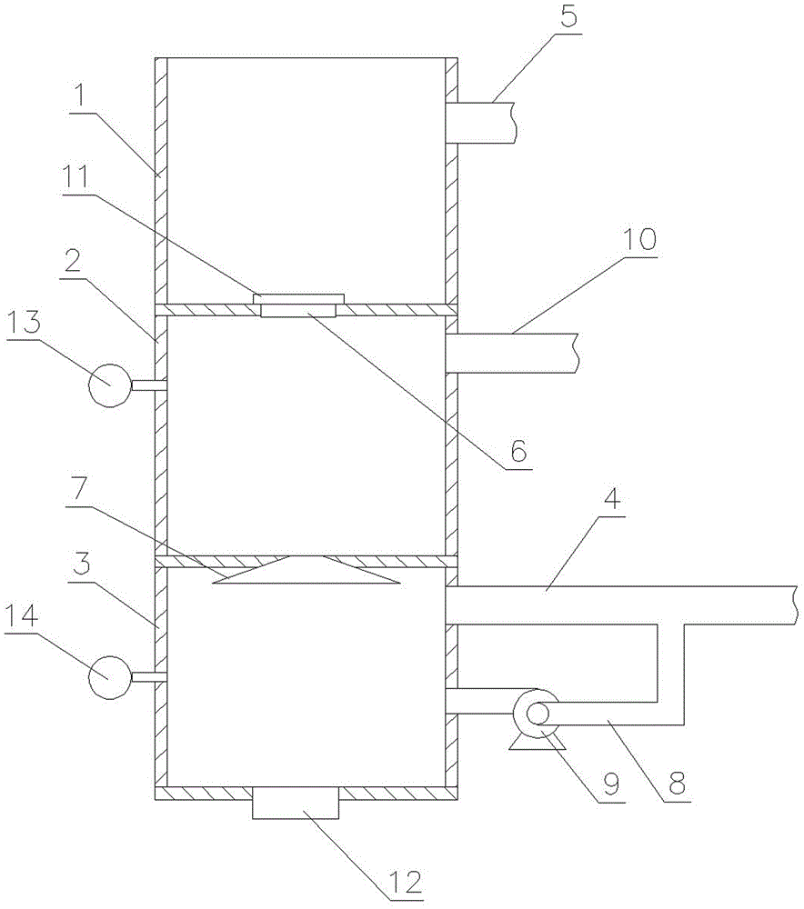
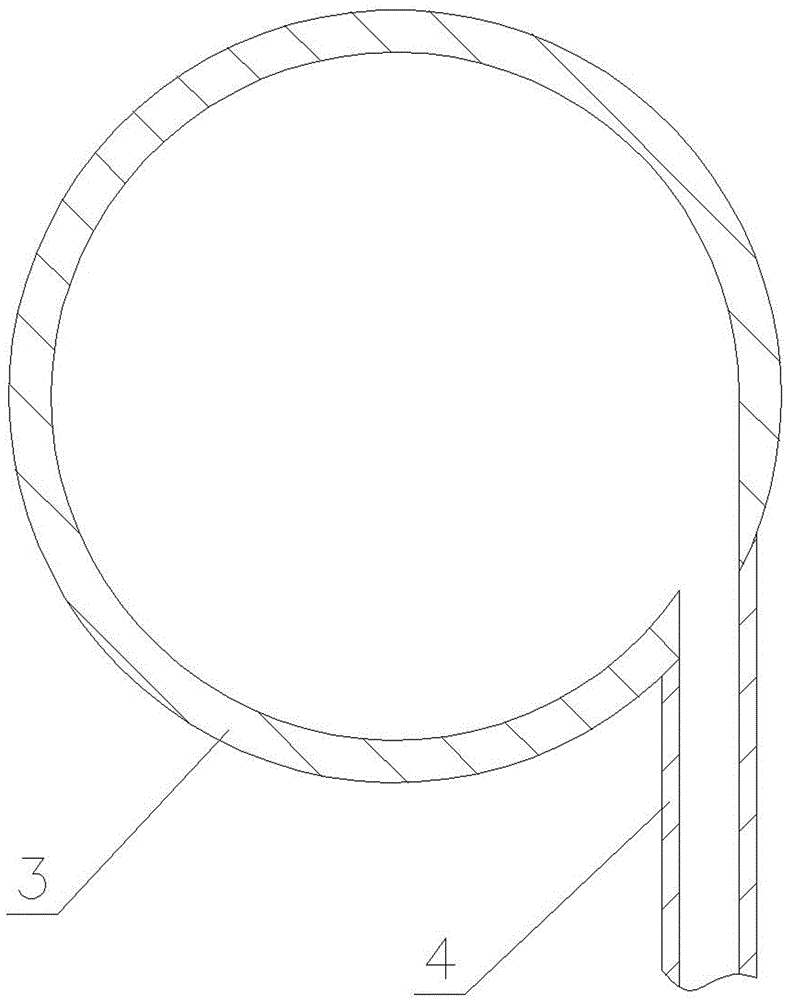
[0023] as attached figure 1 and 2 As shown, a rapid liquid nitrogen ice-making device includes a water storage tank 1, a temperature-regulating tank 2 arranged below or on the side of the water storage tank 1, an ice-making tank 3 arranged below or on the side of the temperature-regulating tank 2, and a The first low-temperature nitrogen inlet pipe 4 connected to the ice tank 3, the water storage tank 1 is used to store the fresh water or sea water needed for ice making, and the water storage tank 1 is provided with a water outlet 6 communicating with the temperature adjustment tank 2, and the water outlet 6 The water outlet 6 is provided with a switch 11 that can open and close the water outlet 6. By opening the switch 11, the water in the water storage tank 1 is controlled to flow into the temperature regulating tank 2. When the water in the temperature re...


PUM


Abstract

The invention discloses a liquid nitrogen rapid-icing device. The liquid nitrogen rapid-icing device comprises a water storage tank, a temperature regulating tank arranged under or on one side of the water storage tank, an icing tank arranged under the temperature regulating tank, and a first low-temperature nitrogen inlet pipe communicating with the icing tank. The water storage tank is provided with a water outlet communicating with the temperature regulating tank. A spraying nozzle capable of spraying water into the icing tank is arranged at the bottom or the side portion of the water storage tank. A cold air circulating pipeline is arranged between the icing tank and the first low-temperature nitrogen inlet pipe which is arranged in the tangential direction of the circumference of the inner wall of the icing tank. Water is cooled in the temperature regulating tank, so that flow control is realized conveniently; water temperature of the temperature regulating tank is regulated to the critical temperature at which water is about to coagulate into ice, the water can coagulate into ice particles rapidly by making contact with liquid nitrogen while being sprayed, and the obtained ice particles are uniform and regular. The liquid nitrogen rapid-icing device has a high cold source utilization rate, can achieve volume-controllable icing, can meet the icing demand and is particularly suitable for marine operation needing long-distance refrigerated shipment, and the ice particles can be prepared immediately once being required.

Description

technical field [0001] The invention relates to an ice making device, in particular to a fast liquid nitrogen ice making device. Background technique [0002] There are many types of existing ice-making devices, most of which are used in refrigerators, and there is no fast ice-making device with an independent structure. When the weather temperature is high and some things need to be transported long distances, a large amount of ice is often added Keeping fresh in blocks, such as seafood and other ingredients, increases the cost and difficulty of transportation on the one hand, and has limitations on the convenience of transportation. It is difficult to ensure the degree of melting of ice cubes, and ice cubes cannot be made at will. Especially for fishing operations on seas and lakes where the water source is readily available, it is necessary to carry a large amount of ice on board, occupying the load space of the ship, and it is also necessary to ensure that it returns to ...

Claims


Application Information

Patent Timeline
Patent Type & Authority Applications(China)
IPC IPC(8): F25C1/00
CPCF25C1/00F25C2700/00
Inventor 何建东范金城
Owner 何建东
Why Eureka
Try Eureka