Eureka AIR delivers breakthrough ideas for toughest innovation challenges, trusted by R&D personnel around the world.

Damping and noise reduction base used for transformer

A transformer and noise reduction technology, which is applied in the field of transformers, can solve problems affecting residents' health, increasing voltage, affecting residents' daily life, etc., and achieves the effects of simple structure, improved shock and noise reduction effects, and convenient installation

Inactive Publication Date: 2018-07-24
合肥云智物联科技有限公司
View PDF4 Cites 1 Cited by
  • Summary
  • Abstract
  • Description
  • Claims
  • Application Information

AI Technical Summary

Problems solved by technology

[0003] The role of the transformer is multifaceted. It can not only increase the voltage to send electric energy to the power consumption area, but also reduce the voltage to the voltage of all levels to meet the needs of power consumption. As a kind of power equipment for raising and lowering voltage, the application of transformers It is very extensive. With the development of urbanization and the expansion of scale, more and more transformers are used in urban and rural residential areas and commercial areas, but usually most of the transformers are directly installed in places that are relatively close to urban and rural residential areas and commercial areas. It will lead to the relatively serious vibration and noise generated by the transformer during operation and spread to the surrounding through the rigid structure of the transformer body and adjacent building structures, which will affect the daily life of residents, and more seriously affect the health of residents

Method used


Image

  • Damping and noise reduction base used for transformer
  • Damping and noise reduction base used for transformer
  • Damping and noise reduction base used for transformer

Examples


Embodiment Construction

[0024] The following will clearly and completely describe the technical solutions in the embodiments of the present invention with reference to the accompanying drawings in the embodiments of the present invention. Obviously, the described embodiments are only some, not all, embodiments of the present invention. Based on the embodiments of the present invention, all other embodiments obtained by persons of ordinary skill in the art without creative efforts fall within the protection scope of the present invention.

[0025] In the description of the present invention, it should be understood that the terms "opening", "upper", "lower", "top", "middle", "inner", "surrounding", etc. indicate orientation or positional relationship, and only It is for the convenience of describing the present invention and simplifying the description, but does not indicate or imply that the components or elements referred to must have a specific orientation, be constructed and operated in a specific ...


PUM


Abstract

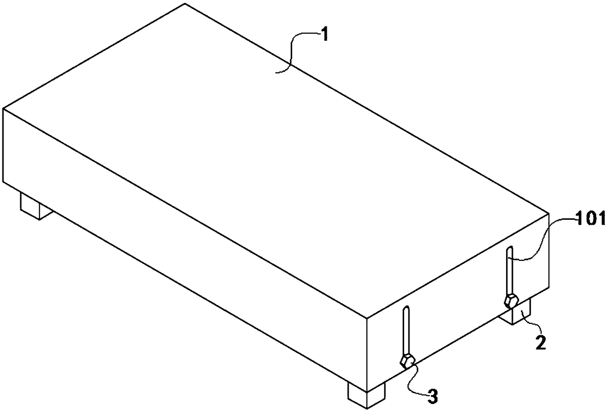
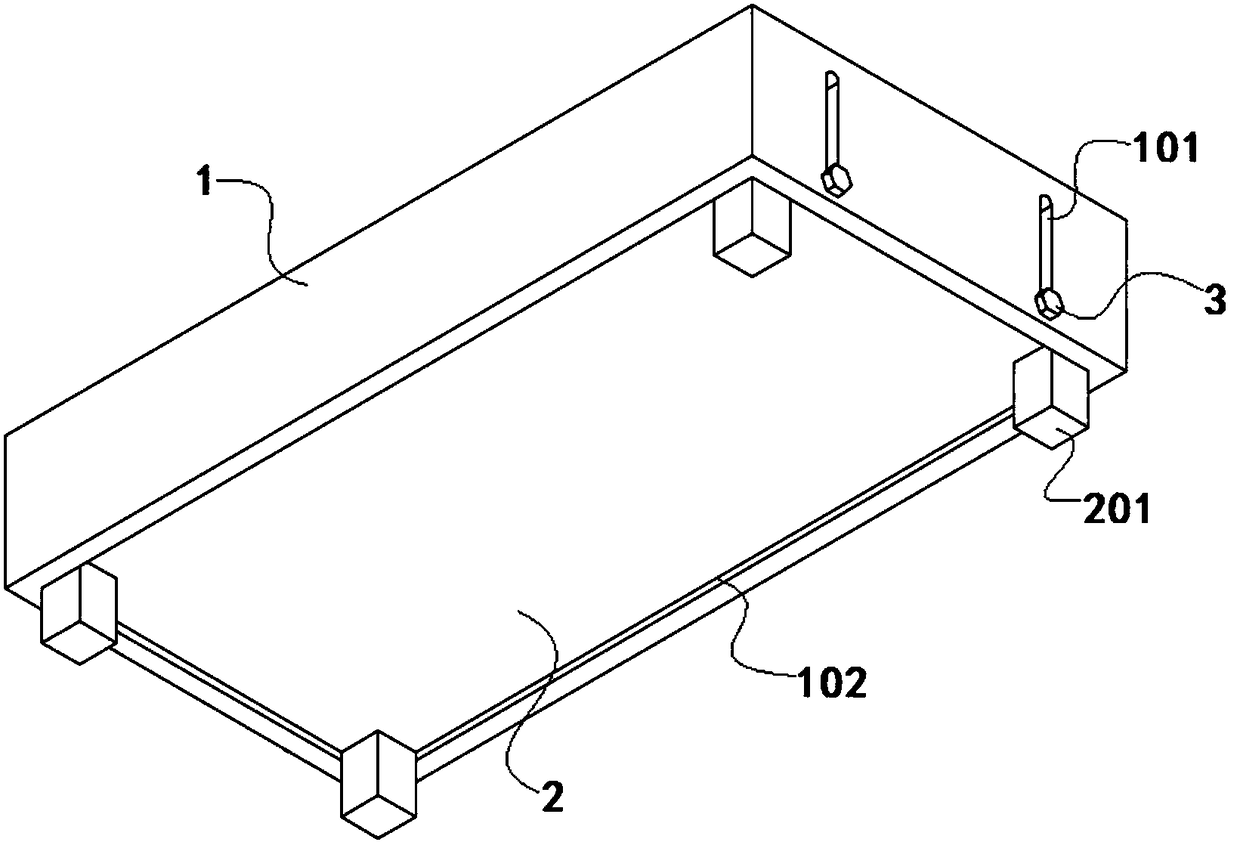
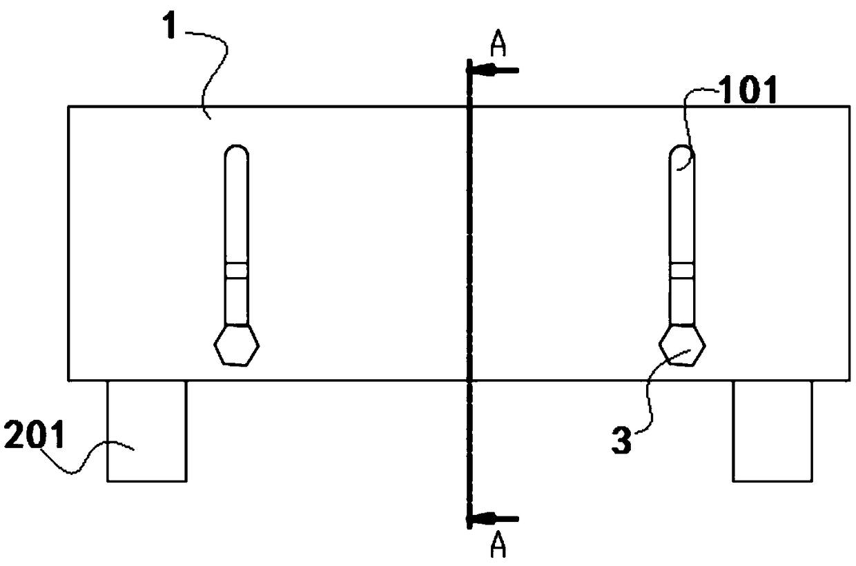
The invention discloses a damping and noise reduction base used for a transformer, and relates to the field of the transformer. The damping and noise reduction base comprises a mounting base and a supporting base; a rectangular groove is formed in the other surface of the mounting base; a plurality of limiting groove channels are formed in the two opposite side surfaces of the rectangular groove side by side; the mounting base is nested on the supporting base; supporting legs are arranged on one surface of the supporting base; threaded holes are formed in the two opposite surfaces of the supporting base respectively; the other surface of the supporting base is connected with a damping plate through damping balls; a damping block and dampers are fixed on the other surface of the damping plate; and the supporting base can perform up and down displacement through matching of limiting bolts and limiting groove channels. By setting the damping balls on the supporting base and by setting thedampers and the damping block on the damping plate, damping can be performed synchronously to realize a multiple-damping effect; the damping and noise reduction base is simple in structure, convenient to mount, and capable of effectively improving the damping and noise reduction effect; and through matching of the limiting groove channels and the limiting bolts, limiting of the mounting base is realized, so that damage of the transformer caused by vibration can be avoided.

Description

technical field [0001] The invention belongs to the field of transformers, in particular to a shock-absorbing and noise-reducing base for transformers. Background technique [0002] Transformer is a device that uses the principle of electromagnetic induction to change AC voltage. The main components are primary coil, secondary coil and iron core (magnetic core). [0003] The role of the transformer is multifaceted. It can not only increase the voltage to send electric energy to the power consumption area, but also reduce the voltage to the voltage of all levels to meet the needs of power consumption. As a kind of power equipment for raising and lowering voltage, the application of transformers It is very extensive. With the development of urbanization and the expansion of scale, more and more transformers are used in urban and rural residential areas and commercial areas, but usually most of the transformers are directly installed in places that are relatively close to urban...

Claims


Application Information

Patent Timeline
Patent Type & Authority Applications(China)
IPC IPC(8): H01F27/06H01F27/33F16F15/04
CPCH01F27/06F16F15/04H01F27/33
Inventor 王培德
Owner 合肥云智物联科技有限公司
Why Eureka
Eureka Blog
Learn More