Piezoelectric stick-slip motor using H-shaped structure and driving method thereof

A driving method, I-shaped technology, applied in the direction of piezoelectric effect/electrostrictive or magnetostrictive motors, generators/motors, electrical components, etc., can solve the problem of unadjustable preload, small output thrust, and poor stability and other problems, to achieve the effect of easy realization, convenient pre-tightening force and simple structure

Active Publication Date: 2018-07-24
CHANGCHUN UNIV OF TECH
View PDF3 Cites 5 Cited by
  • Summary
  • Abstract
  • Description
  • Claims
  • Application Information

AI Technical Summary

Problems solved by technology

[0005] In order to solve the technical problems existing in the existing inertial piezoelectric drive motors, such as short stroke, small output thrust, poor stability, and unadjustable preload, the present invention discloses a piezoelectric stick-slip motor with an I-shaped structure and its driving method.

Method used


Image

  • Piezoelectric stick-slip motor using H-shaped structure and driving method thereof
  • Piezoelectric stick-slip motor using H-shaped structure and driving method thereof
  • Piezoelectric stick-slip motor using H-shaped structure and driving method thereof

Examples


specific Embodiment approach 1

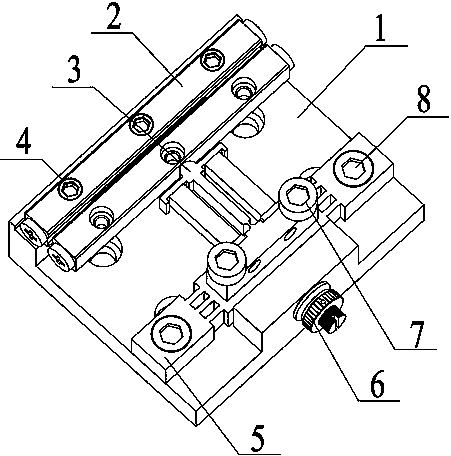
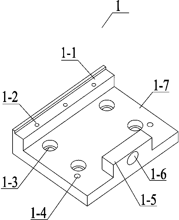
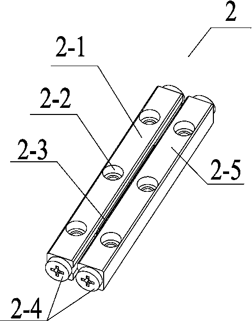
[0022] Specific implementation mode one: combine Figure 1~Figure 7 This embodiment will be described. This embodiment provides a specific embodiment of a piezoelectric stick-slip motor with an I-shaped structure and a driving method thereof. The piezoelectric stick-slip motor with an I-shaped structure and its driving method are composed of a base 1, a double row cross roller guide rail 2, a driving stator 3, a guide rail mounting bolt 4, a loading mechanism 5, a thread pair 6, and a driving stator The mounting bolts 7 and the loading mechanism mounting bolts 8 are composed; the double-row cross roller guide rail 2 is installed on the base 1 through the guide rail mounting bolts 4, and the loading mechanism 5 is installed on the base 1 through the loading mechanism mounting bolts 8 to drive the stator 3 is installed on the loading mechanism 5 by driving the stator mounting bolt 7, and the thread pair 6 is glued and installed on the thread pair installation holes 1-6.

[002...

specific Embodiment approach 2

[0028] Specific implementation mode two: combination Figure 8 This embodiment is described. This embodiment provides a specific implementation of a piezoelectric stick-slip motor with an I-shaped structure and its driving method. The piezoelectric stick-slip motor with an I-shaped structure and its driving method are as follows shown.

[0029] The composite excitation electric signal adopted in the excitation method is realized. The composite excitation electric signal includes a friction regulation wave and a driving wave. By superimposing the friction regulation wave on the fast power-on stage of the driving wave, the I-shaped flexible hinge mechanism is excited in the rapid deformation stage. In the state of micro-pair high-frequency resonance, based on the ultrasonic anti-friction effect, the frictional resistance between the I-shaped flexible hinge mechanism and the movable guide rail in the rapid deformation stage is reduced; the driving wave is a sawtooth wave, and the...


PUM


Abstract

The invention discloses a piezoelectric stick-slip motor using an H-shaped structure and a driving method thereof, which can solves the technical problems that the current piezoelectric stick-slip displacement platforms are complicated in structure, are unstable in the force applied to a guide rail, and the pre-tightening force is inconveniently adjusted. The piezoelectric stick-slip motor includes a base, a guide rail, a drive stator, a guide rail mounting bolt, a loading mechanism, a thread pair, a drive stator mounting bolt, and a loading mechanism mounting bolt. The driving stator utilizesslow extension of stacked piezoelectric ceramics to drive the deformation of a flexible hinge, and reciprocating motion of the guide rail is realized by introducing sawtooth waves into a piezoelectric stack on the basis of the stick-slip principle. The piezoelectric stick-slip motor has the characteristics of simple structure, high stability and large stroke, and has good application prospect inthe field of micro-nano drive and positioning such as optical precise instruments and semiconductor processing.

Description

technical field [0001] The invention relates to a piezoelectric stick-slip motor adopting an I-shaped structure and a driving method thereof, belonging to the field of micro-nano driving and positioning. Background technique [0002] In recent years, with the rapid development of science and technology, the research on micro-nano science and technology has also achieved rapid development. Many technical fields require sub-micron and nano-scale micro-drive technology. Piezoelectric ceramics are a functional material widely used in the field of precision micro drives. They have the advantages of small size, high frequency response, less heat generation, large output force, and no noise. Piezoelectric ceramic drives are widely used in precision drive and positioning technology. The source is used as the driving core in the high-precision driving device. [0003] Due to its unique advantages in resolution, operating frequency, motion speed, frequency response, manufacturing cos...

Claims


Application Information

Patent Timeline
Patent Type & Authority Applications(China)
IPC IPC(8): H02N2/04H02N2/02
CPCH02N2/025H02N2/04
Inventor 程廷海高琪唐晚静曹展豪贾荣房彦旭
Owner CHANGCHUN UNIV OF TECH
Why Eureka
Try Eureka