
Robot holographic 3D image display method

A robot and imaging technology, applied in the direction of instruments, manipulators, image communication, etc., can solve the problem of large image size

Active Publication Date: 2018-07-24
临沂文衡信息技术有限公司
View PDF9 Cites 1 Cited by
  • Summary
  • Abstract
  • Description
  • Claims
  • Application Information

AI Technical Summary

Problems solved by technology

[0002] Existing robot display images are generally displayed through the LCD screen attached to the robot. Generally, the size of the displayed image is at most as large as the screen, and only flat images can be displayed.

Method used


Image

  • Robot holographic 3D image display method
  • Robot holographic 3D image display method
  • Robot holographic 3D image display method

Examples


Embodiment 1

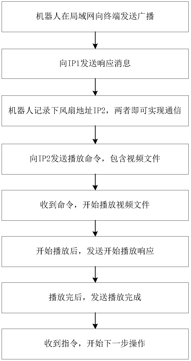
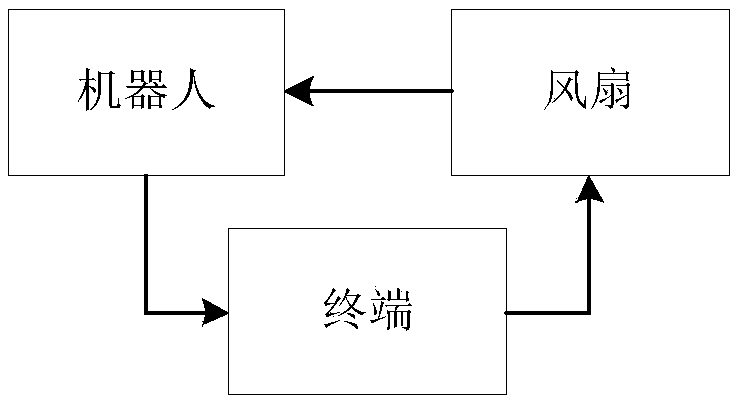
[0030] like Figure 1 to Figure 4 As shown, the robot holographic 3D image display method described in the present invention includes the following steps:

[0031] Step 1: Robot 1 sends a ServerDiscovery broadcast to the terminal address 255.255.255.255 in the local area network, carrying its own network address IP1;

[0032] Step 2: When a broadcast message is received, the peer address IP1 will be obtained from the UDP message;

[0033] Step 3: Send a ServerDispcoveryResponse message to IP1;

[0034] Step 4: Robot 1 records the address IP2 of fan 2, and the two can communicate;

[0035] Step 5: Send the playback command Start_Play_Req to IP2, including the video file;

[0036] Step 6: After receiving Start_Play_Req, start playing the video file;

[0037] Step 7: After starting to play, send the start playing response Start_Play_Rsq;

[0038] Step 8: After playing, send Start_Over_Rsq;

[0039] Step 9: After receiving the instruction, start the next step.

[0040] In s...

Embodiment 2

[0048] With the present invention, the holographic 3D image is played, which is more three-dimensional, vivid and cool than the ordinary LCD screen. If the advertisement is played, the product will leave a deep impression on people. The image size is not limited by the screen size, and it can be used with Robot 1 dynamically interacts to trigger the playback of images, which adds a lot of fun and is a very good means of advertising.

[0049] The size of the image is not limited by the size of the screen, and dynamic interaction with the robot 1 can be used to trigger the playback of the image.

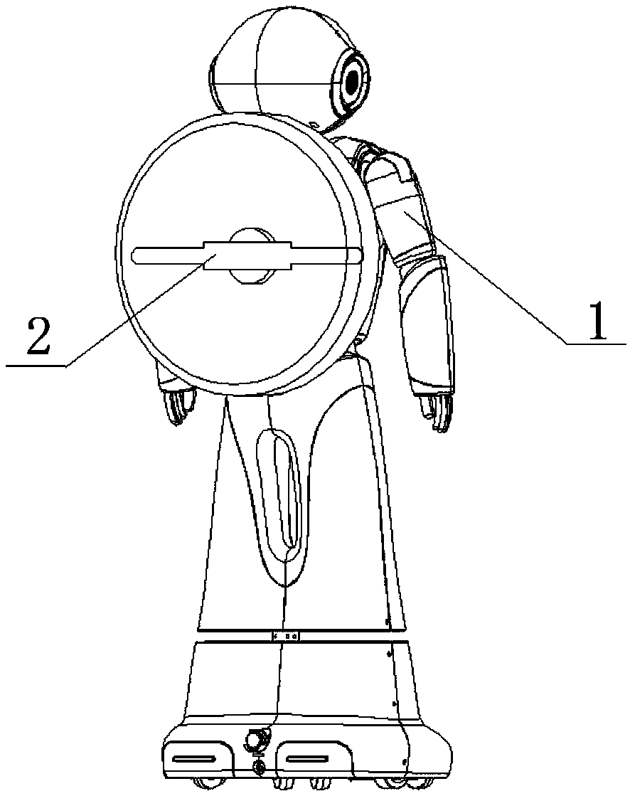
[0050] The beneficial effects of the present invention are: adopting the robot holographic 3D image display method of the present invention, (1) the fan 2 is installed on the robot 1 to display the holographic 3D image; (2) the robot 1 pairs the fan 2 Dynamic management is possible; (3) The fan 2 is triggered to play the holographic 3D image through man-machine dialogue; (4) The specif...


PUM


Abstract

The invention relates to a robot holographic 3D image display method, and belongs to the technical field of data transmission in a communication system. The robot holographic 3D image display method comprises the following steps: step 1: sending, by a robot, a broadcast to a terminal in a local area network, wherein the broadcast carries own network address IP1; step 2: when a broadcast message isreceived, obtaining a peer address IP1 from a UDP message; step 3: sending the message to the IP1; step 4: recording, by the robot, a fan address IP2 to achieve communication; step 5: sending a playing command to the IP2, wherein the playing command comprises a video file; step 6: receiving the playing command and starting to play the video file; step 7: sending playing start response after the playing is started; step 8: sending playing completion after the playing is completed; and step 9: receiving an instruction and starting the next operation. By adoption of the robot holographic 3D image display method, the playing a holographic 3D image by a fan is triggered by a man-machine dialog.

Description

technical field [0001] The invention relates to a robot holographic 3D image display method, which belongs to the technical field of data transmission in communication systems. Background technique [0002] Existing robot display images are generally displayed through the attached LCD screen of the robot. The size of the generally displayed image is at most as large as the screen, and only plane images can be displayed. At present, a technical problem that needs to be solved urgently is to control the start and stop of the fan through WIFI commands to play holographic 3D images. Contents of the invention [0003] In view of the above-mentioned defects in the prior art, the present invention proposes a robot holographic 3D image display method, which triggers the fan to play the holographic 3D image through man-machine dialogue. [0004] The robot holographic 3D image display method of the present invention comprises the following steps: [0005] Step 1: The robot sends a...

Claims


Application Information

Patent Timeline
Patent Type & Authority Applications(China)
IPC IPC(8): H04N21/41H04N21/436H04N21/81G10L15/22B25J11/00
CPCB25J11/0005G10L15/22H04N21/4122H04N21/43615H04N21/812H04N21/816
Inventor 李辉周建炜董学泉
Owner 临沂文衡信息技术有限公司
Learn More