
Paper feeding device for image processing equipment and image processing equipment

An image processing device and paper feeding technology, applied in the imaging field, can solve the problems of non-contact of paper and the inability of pick-up roller to pick up paper, and achieve the effect of reducing paper jam rate, high practical value and economy, and controlling manufacturing cost

Pending Publication Date: 2018-07-27
FUJI XEROX SHANGHAI
View PDF7 Cites 0 Cited by
  • Summary
  • Abstract
  • Description
  • Claims
  • Application Information

AI Technical Summary

Problems solved by technology

[0004] The technical problem to be solved by the present invention is to overcome the defect in the prior art that the pick-up roller of the carton of the image processing equipment may not be in contact with the paper, resulting in that the pick-up roller cannot play the role of picking up the paper, and to provide an image processing equipment. Paper feeding device and image processing equipment

Method used


Image

  • Paper feeding device for image processing equipment and image processing equipment
  • Paper feeding device for image processing equipment and image processing equipment
  • Paper feeding device for image processing equipment and image processing equipment

Examples


Embodiment Construction

[0069] The present invention will be described in detail below in conjunction with the accompanying drawings and specific embodiments. Note that the aspects described below in conjunction with the drawings and specific embodiments are only exemplary, and should not be construed as limiting the protection scope of the present invention.

[0070] In the following description, many specific details are set forth in order to fully understand the present invention, but the present invention can also be implemented in other ways than those described here, so the present invention is not limited by the specific embodiments disclosed below.

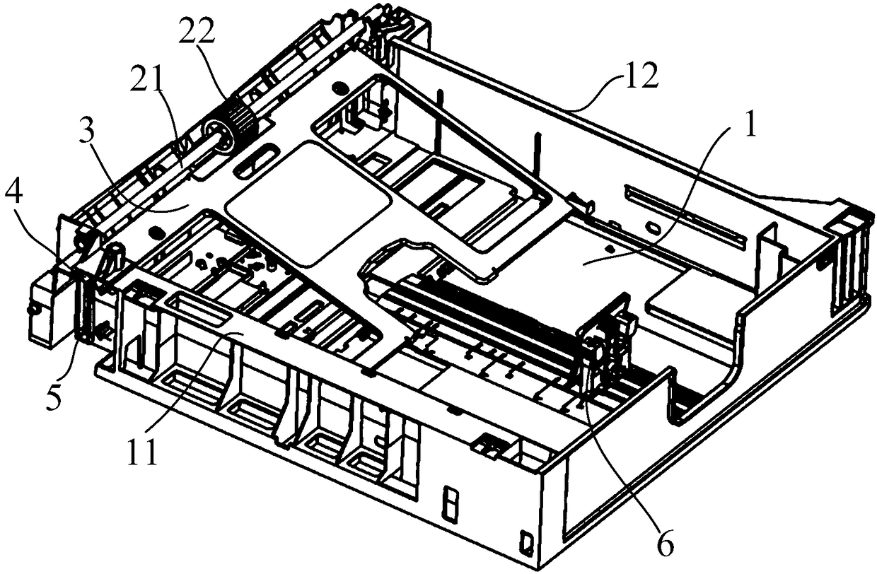
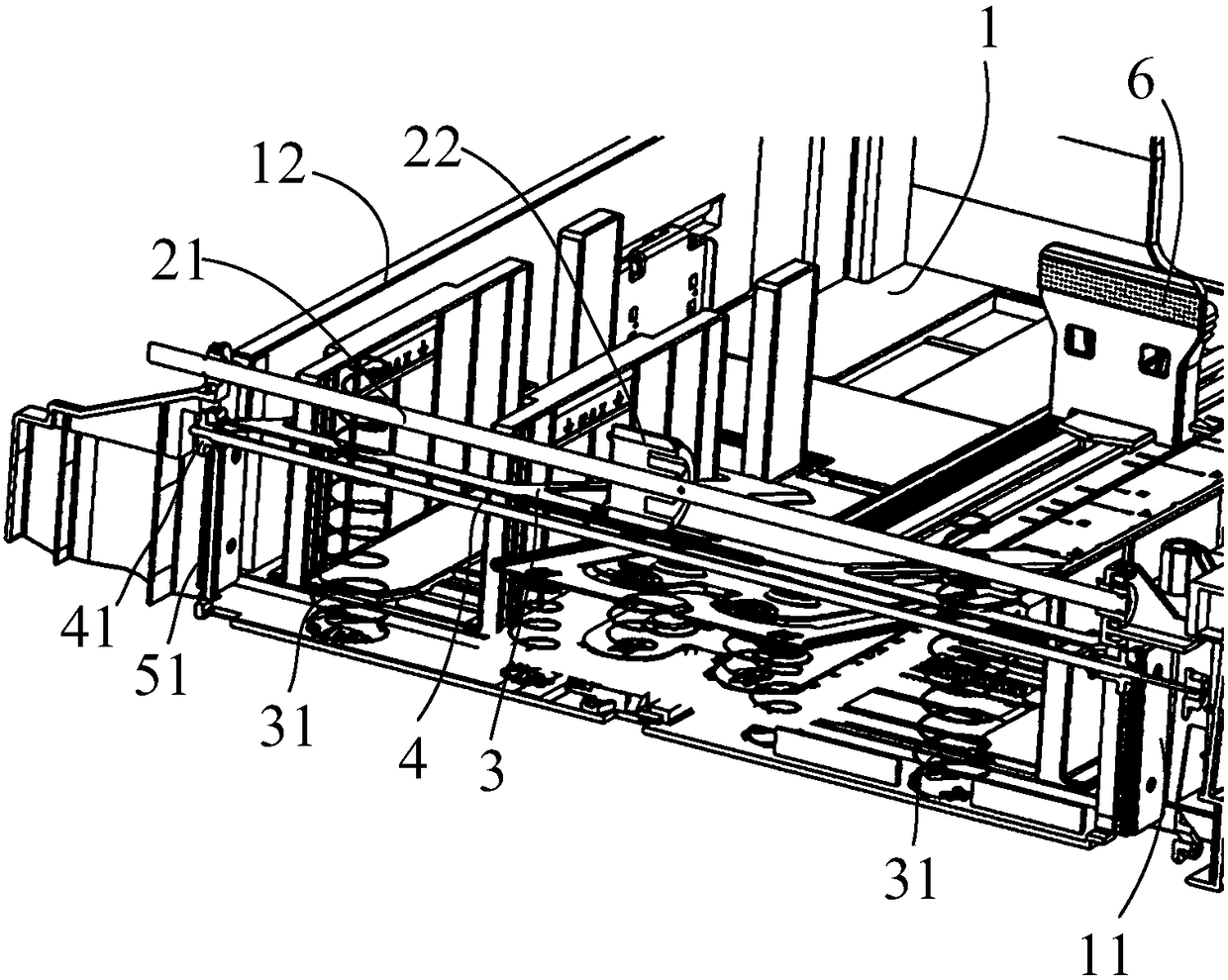
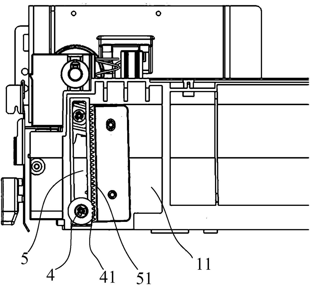
[0071] Such as Figure 1 to Figure 9 As shown, this embodiment provides a paper feeding device for image processing equipment, the paper feeding device mainly includes a paper feeding box 1, a pick-up shaft 21, a pick-up roller 22, a cardboard 3, a guide shaft 4 and a rear guide 6. In this embodiment, the paper feeding device is specifically use...


PUM


Abstract

The invention provides a paper feeding device for image processing equipment and the image processing equipment. The paper feeding device comprises a paper feeding box, a pick-up roller, a pick-up shaft, a paper supporting plate, guide grooves and a guide shaft, wherein the pick-up shaft penetrates through the pick-up roller, and the two ends of the pick-up shaft are arranged on a front frame anda rear frame of the paper feeding box correspondingly; the paper supporting plate is arranged on the paper feeding box and located at the bottom of the pick-up roller; the guide grooves are formed inthe front frame and the rear frame correspondingly in the height direction of the paper feeding box; and the guide shaft is pivoted to the end, close to the pick-up shaft, of the paper supporting plate, the axis of the guide shaft is parallel to the pick-up shaft, the two ends of the guide shaft are arranged in the two guide grooves correspondingly and slide up and down in the height direction ofthe paper feeding box, and the paper supporting plate swings up and down with the guide shaft as a fulcrum so that the front end of to-be-conveyed paper on the paper supporting plate can be located atthe engagement part of the pick-up roller. When different numbers of paper are placed in the paper feeding box, the paper feeding device prevents the contact positions between the pick-up roller andthe front end of the paper from being changed, and the paper sticking rate of the image processing equipment is decreased.

Description

technical field [0001] The invention relates to the field of imaging technology, in particular to a paper feeding device for image processing equipment and the image processing equipment. Background technique [0002] At present, the cartons of image processing equipment such as copiers, especially in FRPD (Friction Retard PadFeeder (feeding device using buffer pad), generally include Nudge Roller (NR, nudge roller) for conveying copy paper, pick-up roller (FR), In a carton with a Retard Pad (RPAD, buffer pad) that is pressed on the pickup roller and a spring that presses the buffer pad on the pickup roller), the position of the front end of the paper will change when the number of papers placed in the carton changes from more to less. . At this time, the pick-up roller may not be in contact with the paper, so the pick-up roller cannot play the role of picking up the paper. In particular, the position of the front end of the paper placed in the large-capacity paper box wil...

Claims


Application Information

Patent Timeline
Patent Type & Authority Applications(China)
IPC IPC(8): B65H1/04B65H3/06B65H3/66
CPCB65H1/04B65H3/0638B65H3/66B65H2701/1131
Inventor 陈银山郭业平
Owner FUJI XEROX SHANGHAI
Learn More