Multichannel direction-finding receiver calibration system and method based on error modification

A technology of error correction and calibration system, which is applied in the monitoring/testing of radio wave direction finders and radio wave directional devices. problem, to achieve the effect of improving the performance of phase measurement, improving the accuracy of phase calibration, and ensuring the performance of direction finding

Active Publication Date: 2018-07-27
CHENGDU TIGER MICROWAVE TECH
View PDF5 Cites 15 Cited by
  • Summary
  • Abstract
  • Description
  • Claims
  • Application Information

AI Technical Summary

Problems solved by technology

[0002] Modern reconnaissance and direction-finding receivers have the characteristics of wide operating frequency band and high frequency points, from hundreds of MHz to tens of GHz, limited by the existing analog-to-digital conversion (ADC) devices, it is impossible to perform digital processing directly at the back end of the antenna, usually The method adopted is to use a superheterodyne receiver to down-convert the radio frequency signal from the antenna to an intermediate frequency, and then process it. The intermediate frequency signal that reaches the phase detection module passes through multiple modules such as the antenna unit, radio frequency channel, and frequency conversion channel. Whether it is the antenna and radio frequency channel at the front end, or the microwave components such as frequency mixing, filtering, and amplification in the frequency conversion channel, the consistency of frequency, phase and amplitude phase characteristics is limited, and the difference in the length of the connecting cable of the local oscillator will also cause a large phase change;
[0003] In engineering implementation, the phase characteristics between channels are not completely consistent, which may lead to a serious decline in the direction finding performance of the direction finding equipment. Accuracy is very important. During the working process of the multi-channel direction-finding receiver, the phase error of each channel is inconsistent due to the influence of the environment, usage time, and device aging. This is the phase calibration of the multi-channel direction-finding receiver. brought great difficulty

Method used


Image

  • Multichannel direction-finding receiver calibration system and method based on error modification
  • Multichannel direction-finding receiver calibration system and method based on error modification

Examples


Embodiment Construction

[0038] The technical solution of the present invention will be further described in detail below in conjunction with the accompanying drawings, but the protection scope of the present invention is not limited to the following description.

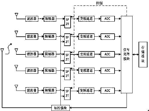
[0039] Such as figure 1 As shown, a multi-channel direction-finding receiver calibration system based on error correction, including a signal processing module, a storage module, a calibration module, a calibration antenna and a plurality of signal receiving components, each signal receiving component is equipped with a front end Corresponding signal receiving antenna;

[0040] The signal receiving component includes a filter, a limiter, a SP2T switch, a frequency conversion channel and an ADC module, the input of the filter is connected to the corresponding signal receiving antenna, and the output of the filter is connected to the SP2T switch through the limiter. The first signal input terminal is connected, the second signal input termin...


PUM


Abstract

The invention discloses a multichannel direction-finding receiver calibration system and method based on error modification. The system includes a signal processing module, a storage module, a standard calibration module, a standard calibration antenna and multiple signal receiving assemblies; each signal receiving assembly consists of a wave filter, an amplitude limiter, an SP2T switch, a frequency conversion channel and an ADC module, wherein the frequency conversion channel of one signal receiving assembly is a reference channel, and the frequency conversion channels of other signal receiving assemblies are phase detection channels; the signal processing module is used for controlling generation of signals of a standard calibration source and switchover of the SP2T switches, processingthe received signals, obtaining phase calibration tables at different temperatures and conducting error modification on the phase calibration tables before use every time. The phase calibration tablesof the signal receiving assemblies in which the phase detection channels are located can be generated at different temperatures, error modification is conducted on the phase calibration tables beforeuse, improvement of the phase calibration precision is facilitated, and the direction-finding performance of a receiver is ensured.

Description

technical field [0001] The invention relates to the field of communication direction finding, in particular to a multi-channel direction finding receiver calibration system and method based on error correction. Background technique [0002] Modern reconnaissance and direction-finding receivers have the characteristics of wide operating frequency band and high frequency points, from hundreds of MHz to tens of GHz, limited by the existing analog-to-digital conversion (ADC) devices, it is impossible to perform digital processing directly at the back end of the antenna, usually The method adopted is to use a superheterodyne receiver to down-convert the radio frequency signal from the antenna to an intermediate frequency, and then process it. The intermediate frequency signal that reaches the phase detection module passes through multiple modules such as the antenna unit, radio frequency channel, and frequency conversion channel. Whether it is the antenna and radio frequency chan...

Claims


Application Information

Patent Timeline
Patent Type & Authority Applications(China)
IPC IPC(8): G01S3/02
CPCG01S3/023
Inventor 王博马爽
Owner CHENGDU TIGER MICROWAVE TECH
Why Eureka
Try Eureka