Equipment for packaging pressure frames

A technology of packaging equipment and pressure, applied in the direction of battery assembly, sustainable manufacturing/processing, climate sustainability, etc., can solve the problem of poor placement of separators and polar plates, troubles, left and right plate orientation Inward tilt and other issues

Active Publication Date: 2018-07-27
GUANGZHOU ZHUOYUE POWER NEW ENERGY CO LTD
View PDF5 Cites 2 Cited by
  • Summary
  • Abstract
  • Description
  • Claims
  • Application Information

AI Technical Summary

Problems solved by technology

[0005] The prior art has the following technical problems: 1. After the pressure frame is placed in the placement part, although the left and right side plates of the pressure frame are positioned by the positioning blocks on both sides of the placement part, they will not tilt outward; The board and the right side board may be inclined inward, which makes it difficult to put the separator and polar plate in; 2. When the packaging pressure is high, it is necessary to drop the separator and polar plate layer by layer. , the pressure box needs to stay for a long time, which is very troublesome

Method used


Image

  • Equipment for packaging pressure frames
  • Equipment for packaging pressure frames
  • Equipment for packaging pressure frames

Examples


Embodiment Construction

[0032] The present invention will be described in further detail below by means of specific embodiments:

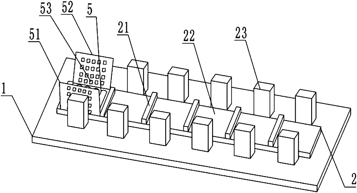
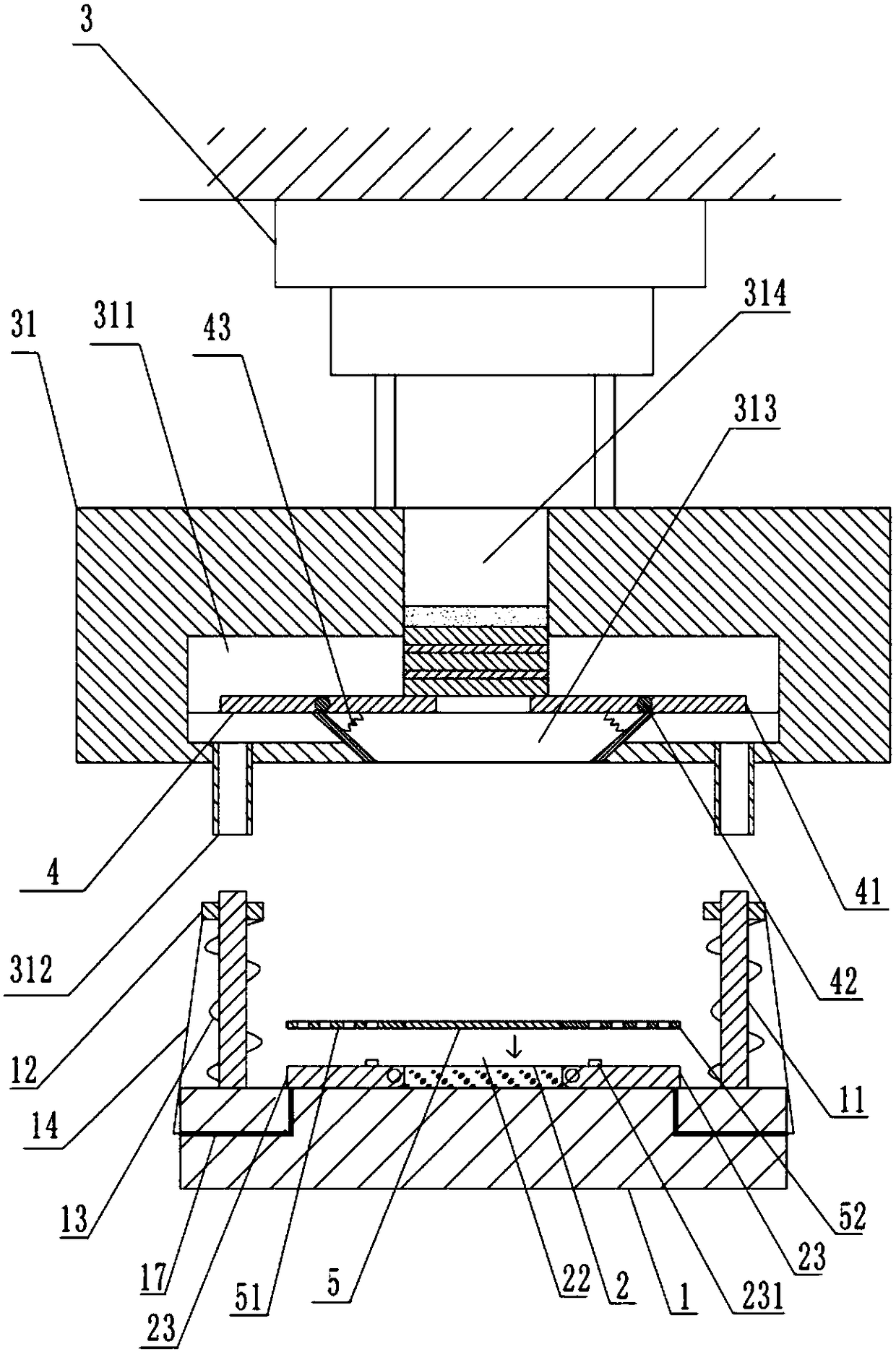
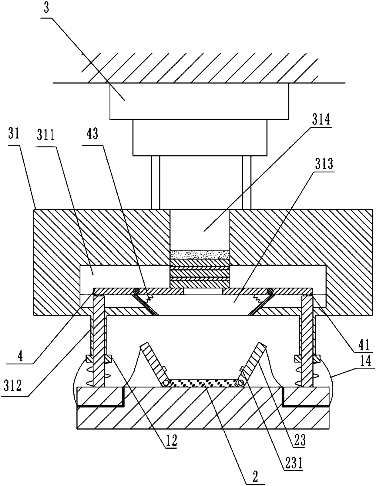
[0033] The reference signs in the drawings of the description include: fixed plate 1, positioning rod 11, limit ring 12, return spring 13, tension line 14, plate body 15, rotating shaft 16, wire hole 17, pressure plate 2, spacer 21 , placement part 22, positioning block 23, positioning protrusion 231, hydraulic cylinder 3, push plate 31, placement cavity 311, limit tube 312, material outlet 313, material inlet 314, first plate 4, second plate 41 , fixed shaft 42, spring 43, base plate 5, left side plate 51, right side plate 52, through hole 53, pressing frame cover 54, pole piece 6, separating plate 61.

[0034] In order to achieve the above object, the basic scheme of the present invention is as follows:

[0035] Such as figure 2 and Figure 6As shown, the pressure frame packaging equipment includes a pressing part, a fixing plate 1 and a pressing plate 2 fixed on th...


PUM


Abstract

The invention relates to the technical field of battery production, and especially relates to a piece of equipment for packaging pressure frames. The equipment comprises a fixing plate and a pressingplate which is fixed on the fixing plate, and the upper surface of the pressing plate is provided with a placing part; double sides of the placing part are provided with locating pieces; the equipmentalso comprises a pressing part on the pressing plate, the pressing part comprises a hydraulic cylinder and a push pedal, and the push pedal is internally provided with a placing cavity; the bottom ofthe pushing pedal is provided with a discharge port; double sides of the discharge port are provided with inserting holes; the end face of the push pedal is provided with a feeding inlet which is communicated with a placing cavity; the placing cavity is internally provided with a switch part; the locating pieces are rotatably connected with the fixing plate, and torsion springs are arranged at the rotation parts of the locating pieces and the fixing plate; positioning convexities are arranged at one side of the locating pieces closed to the pressing plate; locating levers are also arranged onthe fixing plate; the upper part of the locating levers are provided with spacing rings; the fixing plate is internally provided with multiple line passing holes, and the line passing holes are internally provided with taut lines. The scheme can guarantee that the left side plate and the right side plate do not incline inwardly, and reduce retention time of the pressure frame at a packaging process.

Description

technical field [0001] The invention relates to the technical field of battery production, in particular to a pressure frame packaging device. Background technique [0002] In the process of making horizontal batteries, pole pieces need to be stacked. Generally, a separator is placed in the pressure frame first, and then a pole piece is placed, and then stacked upwards in turn until the top one is a separator, and then the pressure frame The cover is closed on the top, thereby realizing the packaging of the pressure frame to the pole piece and the isolation plate. [0003] Such as figure 1 As shown, the existing pressure frame packaging equipment includes a fixed plate 1, the upper surface of the fixed plate 1 is fixed with a pressure plate 2, and the upper surface of the pressure plate 2 is fixed with a plurality of horizontally arranged spacers 21, and the spacers 21 divide the upper surface of the pressure plate 2 into two parts. For multiple placement parts 22 ; positi...

Claims


Application Information

Patent Timeline
Patent Type & Authority Applications(China)
IPC IPC(8): H01M10/04
CPCH01M10/04H01M10/0404Y02P70/50
Inventor 何幸华李政文黎少伟何可立马俊
Owner GUANGZHOU ZHUOYUE POWER NEW ENERGY CO LTD
Why Eureka
Try Eureka