Rotor structure, permanent magnet auxiliary synchronous reluctance motor and electric vehicle

A rotor structure and permanent magnet technology, applied in electric vehicles, motors, electric components, etc., can solve the problems of low motor efficiency, achieve the effects of increasing motor efficiency, reducing vibration, and improving anti-demagnetization ability

Active Publication Date: 2018-07-27
ZHUHAI GREE REFRIGERATION TECH CENT OF ENERGY SAVING & ENVIRONMENTAL PROTECTION
View PDF5 Cites 9 Cited by
  • Summary
  • Abstract
  • Description
  • Claims
  • Application Information

AI Technical Summary

Problems solved by technology

[0003] The main purpose of the present invention is to provide a rotor structure, permanent magnet assisted synchronous reluctance motor and electric vehicle, to solve the problem of low motor efficiency in the prior art

Method used


Image

  • Rotor structure, permanent magnet auxiliary synchronous reluctance motor and electric vehicle
  • Rotor structure, permanent magnet auxiliary synchronous reluctance motor and electric vehicle
  • Rotor structure, permanent magnet auxiliary synchronous reluctance motor and electric vehicle

Examples


Embodiment Construction

[0044] It should be noted that, in the case of no conflict, the embodiments in the present application and the features in the embodiments can be combined with each other. The present invention will be described in detail below with reference to the accompanying drawings and examples.

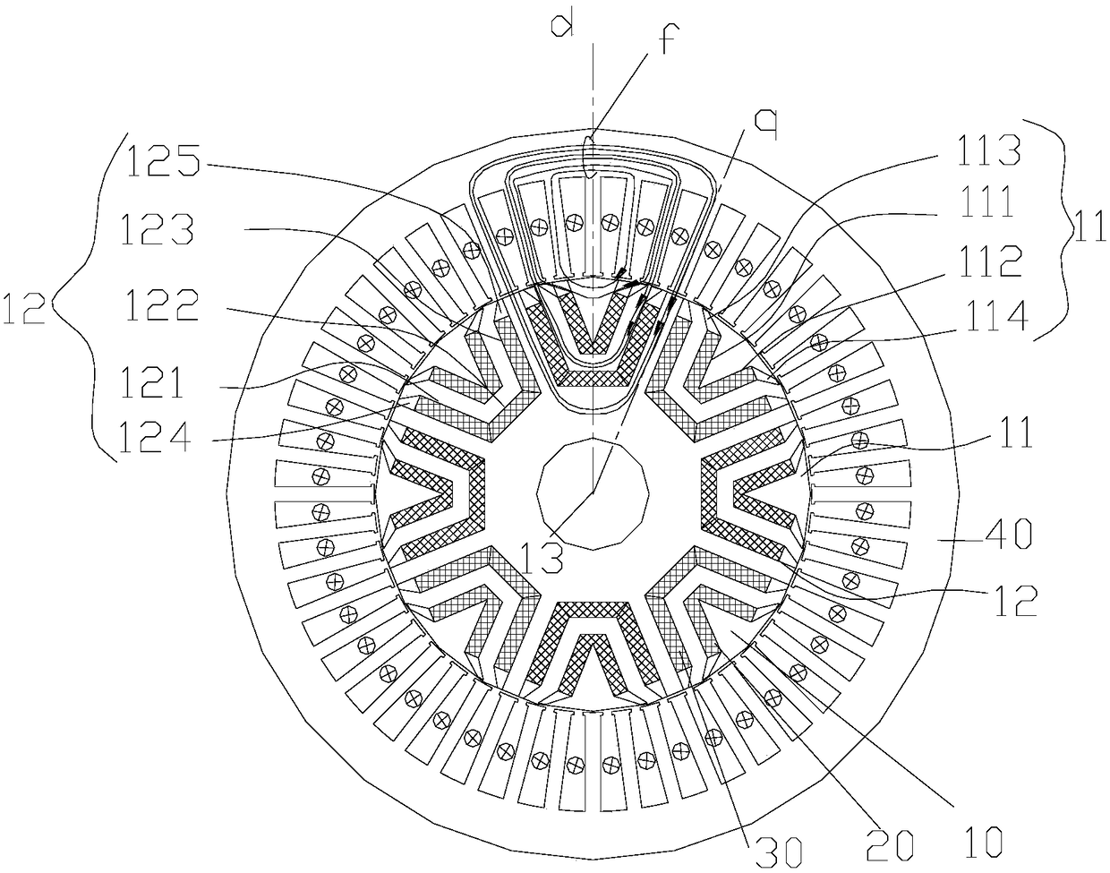
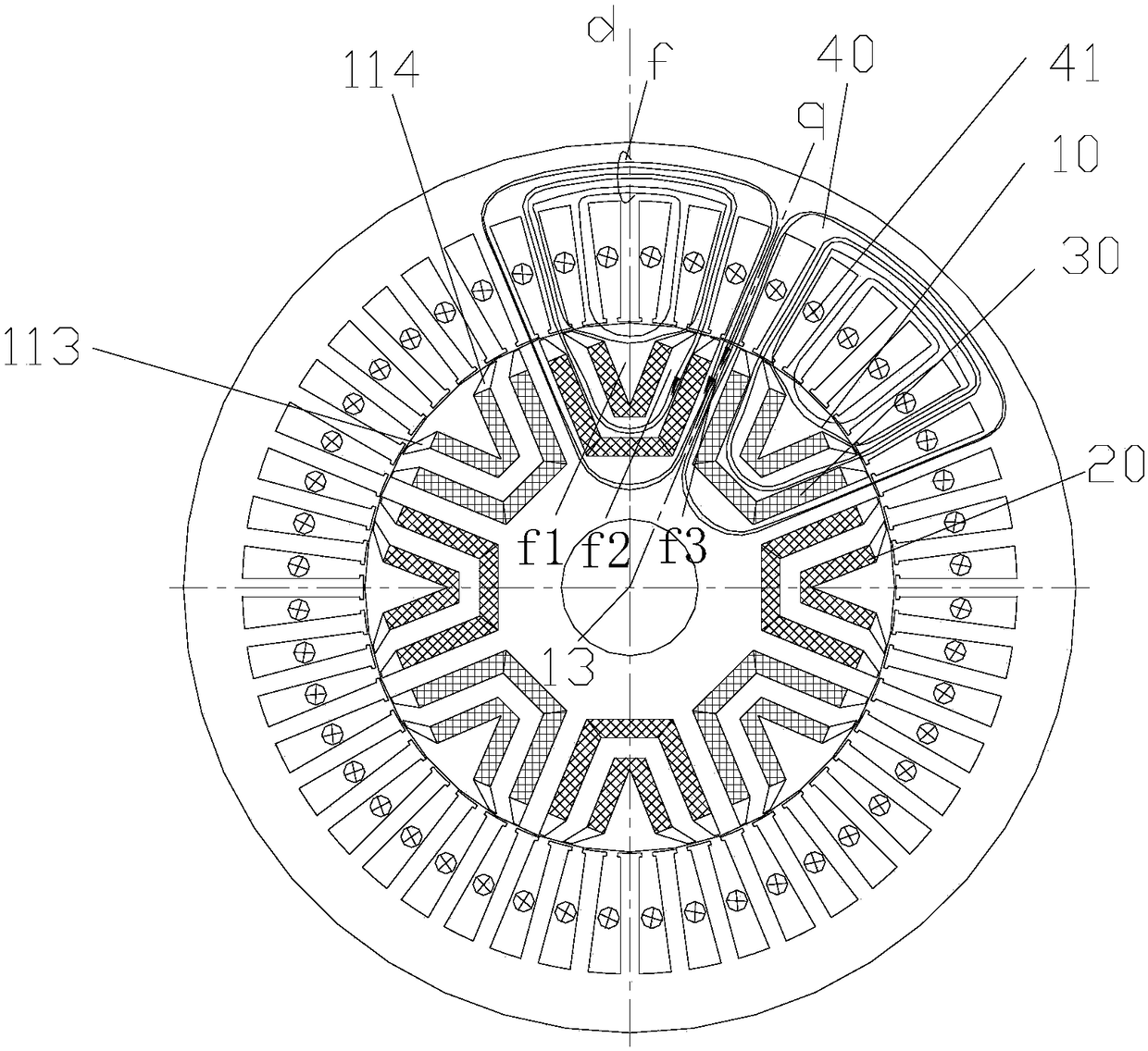
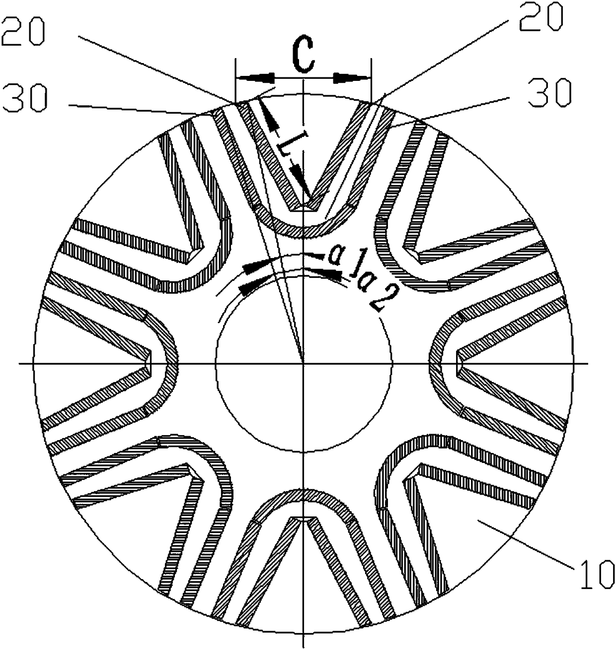
[0045] combine Figure 1 to Figure 12 As shown, according to an embodiment of the present invention, a rotor structure is provided.

[0046] Specifically, the rotor structure includes a rotor body and outer permanent magnets. The rotor body 10 is provided with a set of magnetic steel slots, the set of magnetic steel slots includes an outer layer of magnetic steel slots 11, the outer layer of magnetic steel slots 11 includes a plurality of magnetic steel slot sections, and there are at least two magnetic steel slot sections in the plurality of magnetic steel slot sections The slot segments are oppositely arranged in the radial direction of the rotor body 10 and located on both sides of the strai...


PUM


Abstract

The invention provides a rotor structure, a permanent magnet auxiliary synchronous reluctance motor and an electric vehicle. The rotor structure includes a rotor body and an outer layer permanent magnet. A magnetic steel groove group is disposed on the rotor body, and the magnetic steel groove group includes an outer magnetic steel groove. The outer magnetic steel trough includes a plurality of magnetic steel trough sections. At least two of the plurality of magnet steel trough segments are disposed opposite each other in the radial direction of the rotor body and are located on both sides ofthe straight axis of the rotor body. The outer permanent magnet is disposed in the magnetic steel slot section. Wherein the outer permanent magnets located in the two oppositely disposed magnetic steel trough sections have a length L, and the maximum distance between the two oppositely disposed magnetic steel trough sections is C, among them, 0.8 * C<= L. By arranging the outer magnetic steel troughs of the magnetic steel trough group on the rotor body, more permanent magnets are placed in the unit rotor volume, resulting in a larger permanent magnet torque, improving motor q-axis inductance,increasing motor efficiency, reducing motor torque ripple, motor vibration and noise, and improving motor demagnetization capability.

Description

technical field [0001] The invention relates to the technical field of motor equipment, in particular to a rotor structure, a permanent magnet assisted synchronous reluctance motor and an electric vehicle. Background technique [0002] Electric vehicles have the characteristics of energy saving and environmental protection, and have been developed rapidly. In order to achieve the functions of high power density and high efficiency of the existing electric vehicle drive motors, more and more motors use high-performance rare earth permanent magnet motors. Rare-earth permanent magnet motors can achieve high efficiency and high power density, mainly relying on high-performance rare-earth permanent magnets. Currently, NdFeB rare-earth permanent magnets are the most widely used. However, rare earth is a non-renewable resource, the price is relatively expensive, and the price of rare earth fluctuates greatly, resulting in high production costs of electric vehicle drive motors, whi...

Claims


Application Information

Patent Timeline
Patent Type & Authority Applications(China)
IPC IPC(8): H02K1/27H02K29/03
CPCH02K1/2766H02K29/03H02K2213/03H02K1/2773Y02T10/64B60K1/00
Inventor 黄辉胡余生陈彬肖勇童童卢素华
Owner ZHUHAI GREE REFRIGERATION TECH CENT OF ENERGY SAVING & ENVIRONMENTAL PROTECTION
Why Eureka
Try Eureka