Synchronous reluctance motor rotor structure and related parts manufacturing method

A technology of synchronous reluctance motor and rotor structure, applied in the direction of magnetic circuit rotating parts, magnetic circuit shape/style/structure, chemical instruments and methods, etc., can solve the problem that the inductance difference cannot be made larger, and achieve a huge social Benefit and economic benefit, improve electromagnetic performance, excellent effect

Active Publication Date: 2016-09-14
JIANGXI INST OF RARE EARTHS CHINESE ACAD OF SCI
View PDF7 Cites 0 Cited by
  • Summary
  • Abstract
  • Description
  • Claims
  • Application Information

AI Technical Summary

Problems solved by technology

Since the q-axis inductance of the prior art motor cannot be increased very much, the difference between the inductance Lq and Ld cannot be made larger

Method used


Image

  • Synchronous reluctance motor rotor structure and related parts manufacturing method
  • Synchronous reluctance motor rotor structure and related parts manufacturing method
  • Synchronous reluctance motor rotor structure and related parts manufacturing method

Examples


Embodiment Construction

[0021] In order to understand the technical content of the present invention more clearly, the following examples are given in detail. In this case, the same components are provided with the same reference numerals.

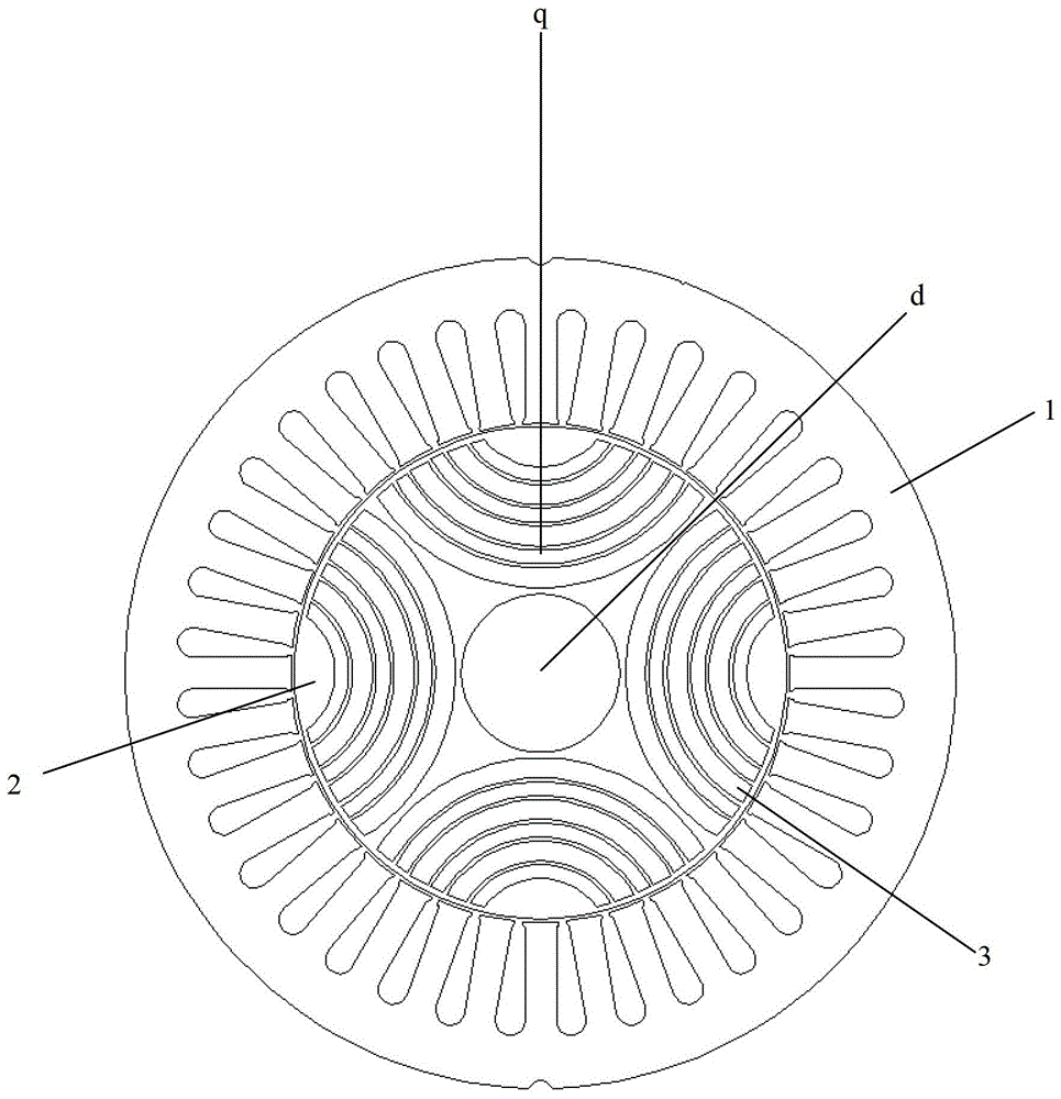
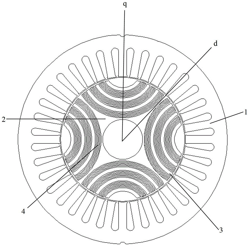
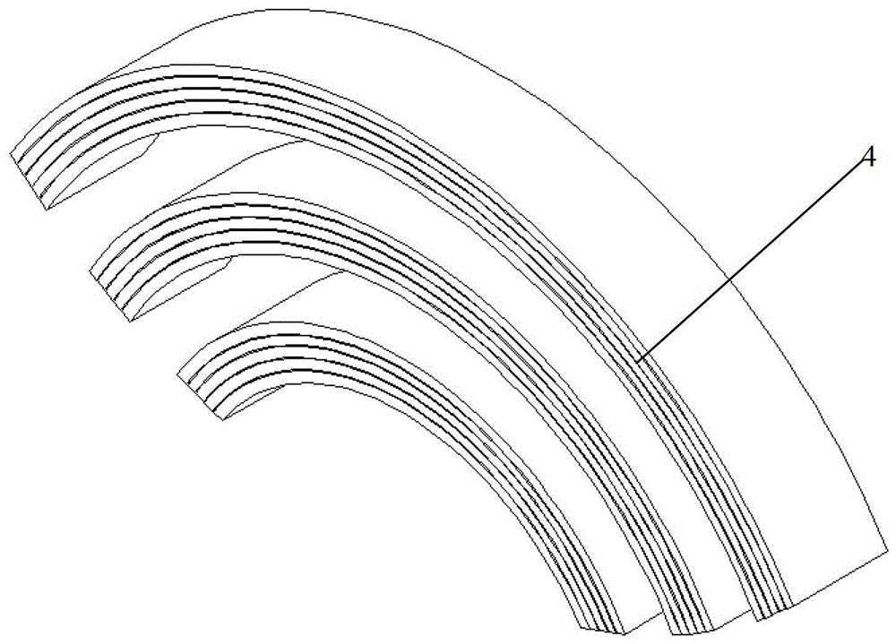
[0022] See Figure 2-Figure 3 As shown, the synchronous reluctance motor rotor structure of the present invention includes a grid-type reluctance motor rotor 2 and an ultra-thin magnetic material lamination element 4, and the ultra-thin magnetic material lamination element 4 is filled in the grid-type reluctance motor rotor 2 grid slot 3.

[0023] The number of the ultra-thin magnetic material lamination elements 4 can be determined according to needs. Preferably, the number of the ultra-thin magnetic material lamination elements 4 is more than 2, which are respectively filled in the different parts of the grid reluctance motor rotor 2. grid slot 3. See figure 2 As shown, in the specific embodiment of the present invention, the number of the ultra-thin magne...


PUM

PropertyMeasurementUnit
thicknessaaaaaaaaaa
thicknessaaaaaaaaaa
thicknessaaaaaaaaaa

Abstract

The invention relates to a synchronous reluctance motor rotor structure. The synchronous reluctance motor rotor structure comprises a grid type reluctance motor rotor and extreme-thin magnetic material stacking elements, wherein the extreme-thin magnetic material stacking elements are filled in grid grooves of the grid type reluctance motor rotor. Preferably, the number of the extreme-thin magnetic material stacking elements is more than two, and the extreme-thin magnetic material stacking elements are respectively filled into the different grid grooves or spaced grid grooves. The extreme-thin magnetic material stacking elements are formed through stacking, paint dipping and curing of the extreme-thin magnetic material stacking elements. The thickness of the extreme-thin magnetic material stacking elements is smaller than 0.1mm, and the extreme-thin magnetic material stacking elements are made of extreme-thin amorphous alloy materials. The invention further relates to a method for manufacturing the extreme-thin magnetic material stacking elements. The synchronous reluctance motor rotor structure is ingenious in structural design, simple in structure, capable of effectively improving the mechanical strength and electromagnetic performance of the grid type reluctance motor rotor, high in production efficiency and stable in product quality, is suitable for large-scale popularization and application, has powerful pushing effect on an efficient energy-saving motor and produces large social benefit and economic benefit.

Description

technical field [0001] The invention relates to the technical field of synchronous reluctance motors, in particular to the technical field of synchronous reluctance motor rotors, in particular to a synchronous reluctance motor rotor structure and a method for manufacturing related components. Background technique [0002] In recent years, the energy crisis is imminent, but the world's energy consumption is increasing at a tremendous rate every year. The way out to overcome the energy crisis is to vigorously develop renewable energy, and it is an inevitable trend to seek energy-efficient and power-saving equipment. [0003] Since electric motors are the most important energy-consuming equipment in all walks of life in the world, how to manufacture more efficient and energy-saving electric motors has always been the direction of joint efforts of experts and scholars from all over the world. The permanent magnet synchronous reluctance permanent magnet (SR-PM) motor does not use...

Claims


Application Information

Patent Timeline
Patent Type & Authority Patents(China)
IPC IPC(8): H02K1/24H02K1/02B32B38/08
Inventor 罗建王国栋罗升
Owner JIANGXI INST OF RARE EARTHS CHINESE ACAD OF SCI
Why Eureka
Try Eureka