Array pulse load power supply circuit and control method thereof
A pulse load and power supply circuit technology, which is applied in the direction of control/regulation system, electrical components, and adjustment of electrical variables, etc., to achieve the effects of improving reliability and service life, high efficiency, and excellent response speed
- Summary
- Abstract
- Description
- Claims
- Application Information
AI Technical Summary
Problems solved by technology
Method used
Image
Examples
Embodiment
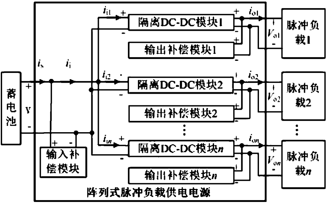
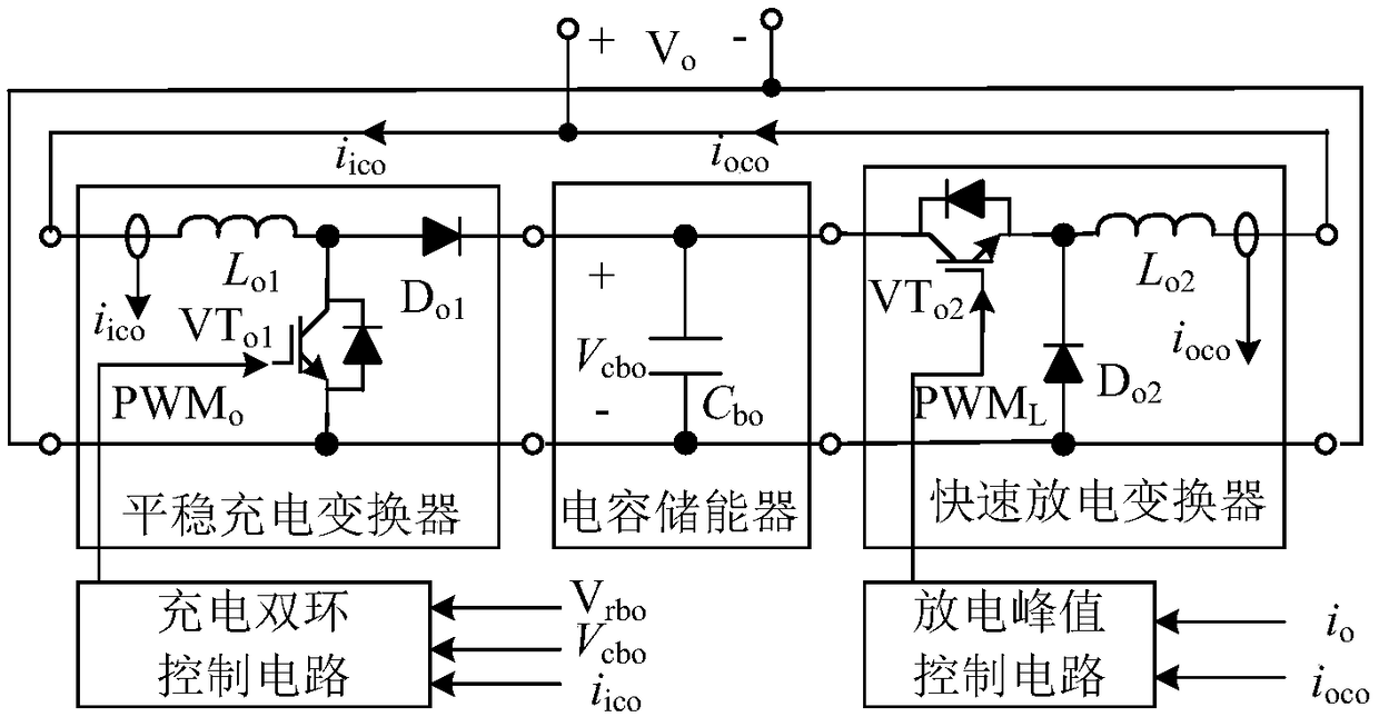
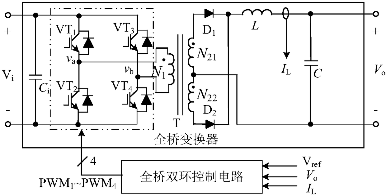
[0086] Embodiment: A pulse battery device composed of an isolated DC-DC module and a pulse load is constructed by using the software Matlab / Simulink according to the principle described in this patent. input V i =100V, output V o =50V, in the isolated DC-DC module, the frequency is 20kHz, the inductance L=400μH, the capacitance C=3000μF; in the output compensation module, the frequency of the smooth charge converter and the fast discharge converter is 40kHz, the inductance L o1 =200μH, capacitance C bo =2000μF, V cbo =75V, inductance L o2 =10μH; isolated DC-DC module adopts Figure 10 For the full-bridge double-loop control parameters shown, the output compensation module adopts Figure 11 The charging double-loop control parameters are shown.
[0087] Under the peak current time / period / peak current of pulse load = 1ms / 10ms / 50A, the average value of the output inductor current of the full-bridge converter is 5.5A, the peak-to-peak value of the ripple current is 0.1A, and...
PUM
 Abstract
Description
Claims
Application Information
 - R&D
- Intellectual Property
- Life Sciences
- Materials
- Tech Scout
- Unparalleled Data Quality
- Higher Quality Content
- 60% Fewer Hallucinations
Browse by: Latest US Patents, China's latest patents, Technical Efficacy Thesaurus, Application Domain, Technology Topic, Popular Technical Reports.
© 2025 PatSnap. All rights reserved.Legal|Privacy policy|Modern Slavery Act Transparency Statement|Sitemap|About US| Contact US: help@patsnap.com


