
Direct current offset cancellation circuit of single-frequency continuous wave radar with zero intermediate frequency receiver structure

A zero-IF receiver and single-frequency continuous wave technology, applied in the field of DC offset cancellation circuit, can solve problems such as local oscillator leakage, baseband amplifier analog-to-digital converter saturation, high hardware cost, etc.

Pending Publication Date: 2021-09-10
中山艾朗格科技有限公司
View PDF1 Cites 0 Cited by
  • Summary
  • Abstract
  • Description
  • Claims
  • Application Information

AI Technical Summary

Problems solved by technology

This system avoids the problem of DC offset causing saturation of the baseband amplifier and analog-to-digital converter, but the radar IQ requires two baseband amplifiers, two 16-bit ADCs and one 16-bit DAC, a comparator, and a DC controller for each channel , the system is complex and pays a high hardware price
Zhejiang University (Patent No., CN 110133642 A) proposed a DC offset compensation method for radar sensors. This method is only aimed at the signal processing field of DC offset. This method cannot avoid excessive DC offset from causing baseband amplifier and hardware issues with analog-to-digital converter saturation
[0004] The zero-IF receiver of the radar mixes the echo signal and the carrier signal of the same frequency, and directly converts the signal to the baseband. The conversion process does not pass through the intermediate frequency. The system structure is simple and there is no image frequency interference. The problem is that there will be "local oscillator leakage" and "interference self-mixing", which will inevitably cause DC offset problems. Excessive DC offset will cause the saturation of the baseband amplifier or analog-to-digital converter, and the useful signal cannot be amplified. , and even burn the chip

Method used


Image

  • Direct current offset cancellation circuit of single-frequency continuous wave radar with zero intermediate frequency receiver structure
  • Direct current offset cancellation circuit of single-frequency continuous wave radar with zero intermediate frequency receiver structure
  • Direct current offset cancellation circuit of single-frequency continuous wave radar with zero intermediate frequency receiver structure

Examples


Embodiment Construction

[0026] In order to make the object, technical solution and advantages of the present invention clearer, the present invention will be further described in detail below in conjunction with the accompanying drawings and embodiments. It should be understood that the specific embodiments described here are only used to explain the present invention, not to limit the present invention.

[0027] In the drawings of this embodiment, the same or similar symbols correspond to the same or similar components; in the description of the present invention, it should be ", "outside" and other indicated orientations or positional relationships are based on the orientations or positional relationships shown in the drawings, which are only for the convenience of describing the present invention and simplifying the description, rather than indicating or implying that the referred device or element must have a specific Orientation, construction and operation in a specific orientation, so the terms...


PUM


Abstract

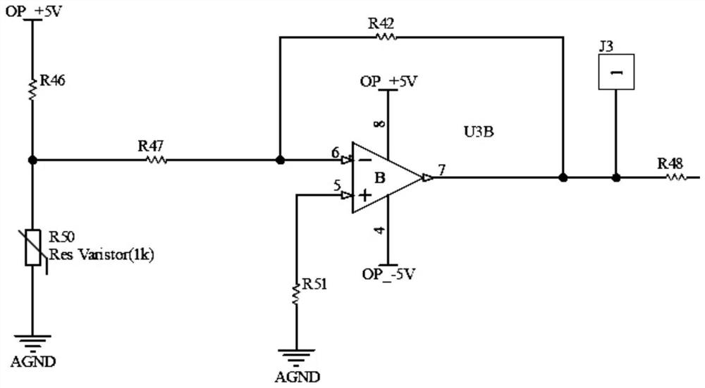
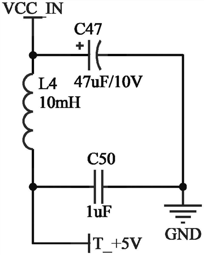
The invention discloses a direct current offset offset circuit of a single-frequency continuous wave radar with a zero intermediate frequency receiver structure. The direct current offset offset circuit comprises a mixer intermediate frequency port, an adjustable direct current offset circuit, a differential amplifier, an anti-aliasing filter and an analog-to-digital converter, the mixer intermediate frequency port is used for accessing a first voltage source voltage division circuit signal and outputting the first voltage source voltage division circuit signal to the differential amplifier; the adjustable direct current offset circuit is used for accessing a second path of voltage source voltage division circuit signal, suppressing power supply voltage ripples and system noise, and outputting the signal to the differential amplifier; the output to the differential amplifier is used for carrying out direct current offset offset on the two paths of voltage source voltage division circuit signals and outputting to the anti-aliasing filter; the anti-aliasing filter is used for filtering signals outside a concerned frequency band, retaining part of useful direct current offset and outputting the useful direct current offset to the analog-to-digital converter; and the analog-to-digital converter is used for converting an analog signal into a digital electrical signal and outputting the digital electrical signal.

Description

technical field [0001] The invention belongs to the technical field of single-frequency continuous-wave Doppler radar, in particular to a DC offset canceling circuit of single-frequency continuous-wave radar with a zero-IF receiver structure. Background technique [0002] The zero-IF receiver has the advantages of simple structure and greatly reduces the phase noise of the local oscillator due to the distance correlation. However, the self-mixing of zero-IF receivers will generate DC offset interference. LO leakage self-mixing is caused by the hardware defect of the component. The leaked LO signal passes through the low-noise amplifier or RF band-pass filter or the self-mixing of the receiving antenna end and the LO signal, and the baseband signal at the IF port Introducing a large DC offset. Also, radar targets that are not moving relative to the radar receiver are considered clutter noise, which can also cause LO leakage in the system. In addition, interfering self-mixi...

Claims


Application Information

Patent Timeline
Patent Type & Authority Applications(China)
IPC IPC(8): G01S7/40
CPCG01S7/4021
Inventor 李根陈庆武王刚
Owner 中山艾朗格科技有限公司
Learn More