
A dimming method for LED drive power supply without electrolytic capacitor

A technology of LED driving and electrolytic capacitors, which is applied in the field of dimming of LED driving power supplies without electrolytic capacitors. It can solve the problems of changing the output current by controlling the on-off of the switching tube, the inability to adjust the output current of the resonant converter, and the limited range of output voltage adjustment. Realize the effects of dimming control, high reliability and suppression of voltage ripple

Inactive Publication Date: 2021-03-02
FUZHOU UNIV
View PDF8 Cites 0 Cited by
  • Summary
  • Abstract
  • Description
  • Claims
  • Application Information

AI Technical Summary

Problems solved by technology

[0004] For a two-stage LED drive power supply consisting of a PFC stage and a constant current resonant converter, since the resonant converter is at the constant current frequency, the output current of the resonant converter is only related to the input voltage and resonance parameters of the resonant network, so it cannot be adjusted by adjusting the frequency For dimming (analog dimming), the output current of the resonant converter cannot be adjusted by changing the resonance parameters in practical applications, and since the resonant converter is a constant current output, the output current cannot be directly changed by controlling the switch tube on and off, so the adjustment Light must be realized by changing the input voltage of the resonant network
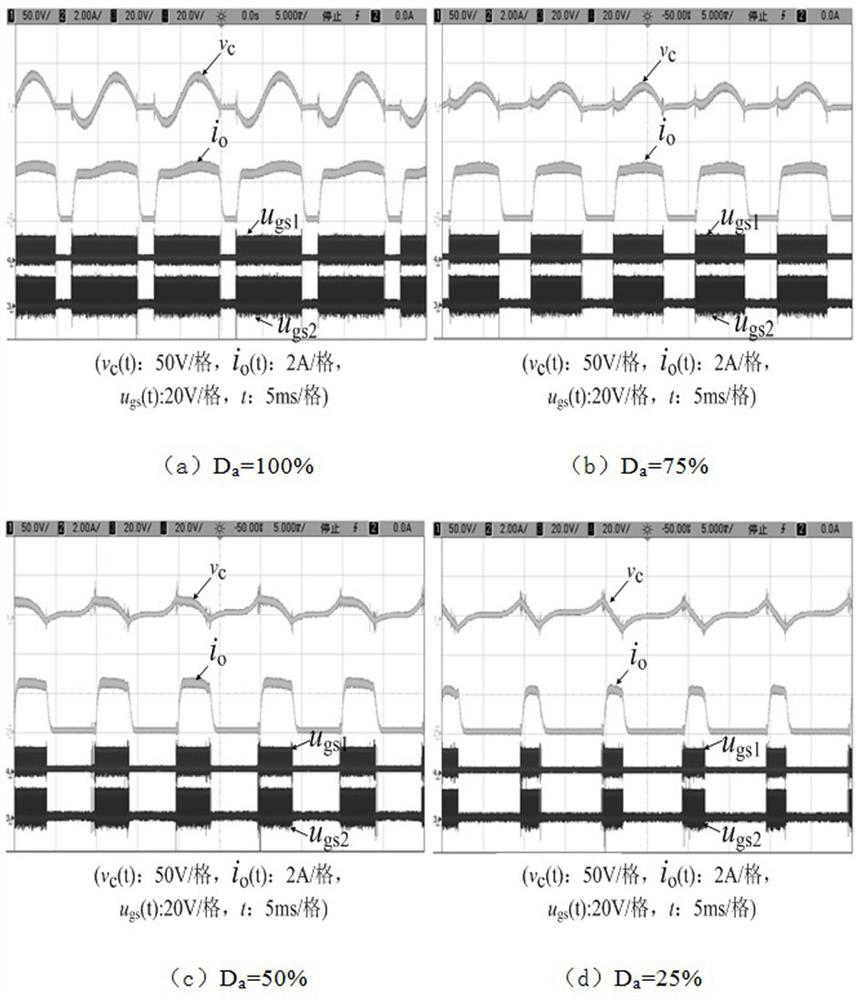
The input voltage of the resonant network has a linear relationship with the output voltage of the PFC, but because the PFC circuit usually uses a Boost converter, the output voltage adjustment range is limited, so only by controlling the constant current resonant converter to work in the pulse density modulation mode, so as to change The input voltage of the resonant network can realize the dimming control of the LED lamp

Method used


Image

  • A dimming method for LED drive power supply without electrolytic capacitor
  • A dimming method for LED drive power supply without electrolytic capacitor
  • A dimming method for LED drive power supply without electrolytic capacitor

Examples


Embodiment Construction

[0019] The technical solution of the present invention will be specifically described below in conjunction with the accompanying drawings.

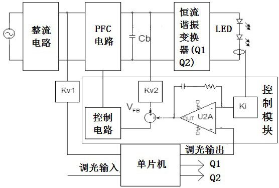
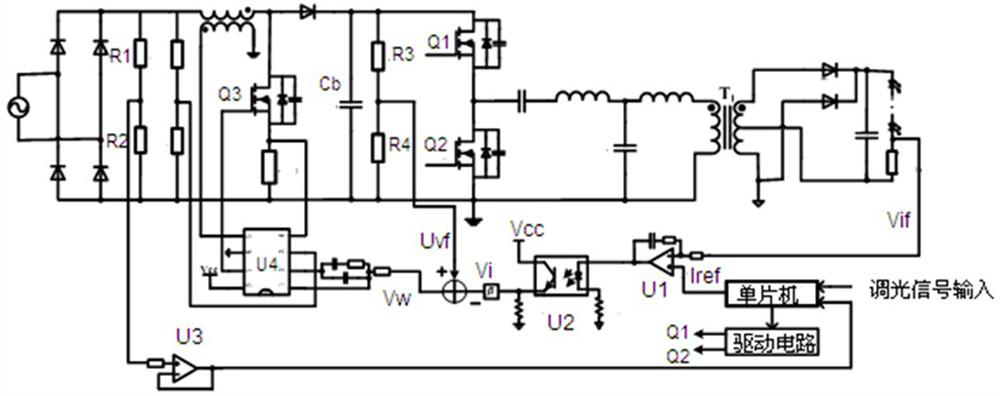
[0020] The invention provides a dimming method for an electrolytic capacitor LED drive power supply. The electrolytic capacitor LED drive power supply is composed of a rectifier circuit, a PFC circuit, an energy storage capacitor, a constant current resonant converter and an LED lamp. The method is controlled by a control unit. Combining the dimming input signal with the PFC input voltage signal to generate a dimming control signal, when the PFC input voltage is greater than the set voltage value V e , the control constant current resonant converter starts to work, after the set time t a Afterwards, the constant current resonant converter stops working, and so on and on, so that the constant current resonant converter works in the pulse density modulation mode, and the LED is driven in the pulse current mode, so as to realize the dimming ...


PUM


Abstract

The invention relates to a dimming method of a non-electrolytic capacitor LED driving power supply. The dimming control signal is generated by combining the dimming input signal with the PFC input voltage signal. When the PFC input voltage is greater than the set voltage value, the constant current resonant converter starts to work. After the set time, the resonant converter Stop working, and so on. The set voltage value, the set time and the set dimming output signal are calculated from the duty cycle of the dimming input signal, the duty cycle of the pulsating current at the rated output current and the PFC input voltage. By adjusting the working time and continuous working time of the constant current resonant converter, the dimming control of the LED lamp is realized, and the voltage ripple of the energy storage capacitor is suppressed. The method of the invention has the advantages of wide dimming range, long service life and high reliability.

Description

technical field [0001] The invention relates to a dimming method of a non-electrolytic capacitor LED driving power supply. Background technique [0002] With the in-depth research on LED-related technologies, the application range of LED is becoming wider and wider, gradually becoming the mainstream lighting equipment, and people's demand for energy saving, personalized lighting, intelligent control, etc. requires that LED must have dimming function, and dimming During the process, the power consumption and temperature of the LED will be reduced, which is conducive to improving the life and reliability of the LED lamp. Therefore, the research on the dimming scheme of LED driving power supply is of great significance to the popularization and use of LED. [0003] At present, the research on LED dimming methods mainly focuses on three kinds of thyristor dimming, analog dimming and PWM dimming. Among them, PWM dimming is to change the average brightness of LED by controlling ...

Claims


Application Information

Patent Timeline
Patent Type & Authority Patents(China)
IPC IPC(8): H05B45/10H05B45/345H05B44/00
CPCH05B45/10H05B45/37
Inventor 林国庆徐心靖林梅珍
Owner FUZHOU UNIV
Learn More