
A lock control device for a smart bicycle

A control device and bicycle technology, applied in the direction of bicycle locks, locks controlled by non-mechanical transmission, services based on specific environments, etc., can solve problems such as easy rusting of key parts, poor city environment, and impact, so as to prevent chaos The effect of parking indiscriminately, reducing operation and maintenance costs, and prolonging service life

Active Publication Date: 2020-04-28
杭州速利科技有限公司
View PDF5 Cites 0 Cited by
  • Summary
  • Abstract
  • Description
  • Claims
  • Application Information

AI Technical Summary

Problems solved by technology

[0002] At present, shared bicycles are developing rapidly, which brings convenience to people. At the same time, some behaviors of parking shared bicycles indiscriminately also have a bad impact on the city environment.
At present, the smart locks used for bicycles are still unlocked by traditional cam motor modules combined with metal mechanical structures. The key parts of this kind of locks are prone to rust, which affects the smooth completion of unlocking and locking of bicycles, and often needs to be replaced. The operation and maintenance cost of bicycle delivery enterprises
More importantly, due to its structural characteristics, the current smart bicycle lock cannot realize the electronic fence function and cannot limit the parking position of shared bicycles. If the random parking of shared bicycles cannot be guided and regulated in operation, it will be serious. Affect the launch and promotion of shared bicycles

Method used


Image

  • A lock control device for a smart bicycle
  • A lock control device for a smart bicycle
  • A lock control device for a smart bicycle

Examples


Embodiment

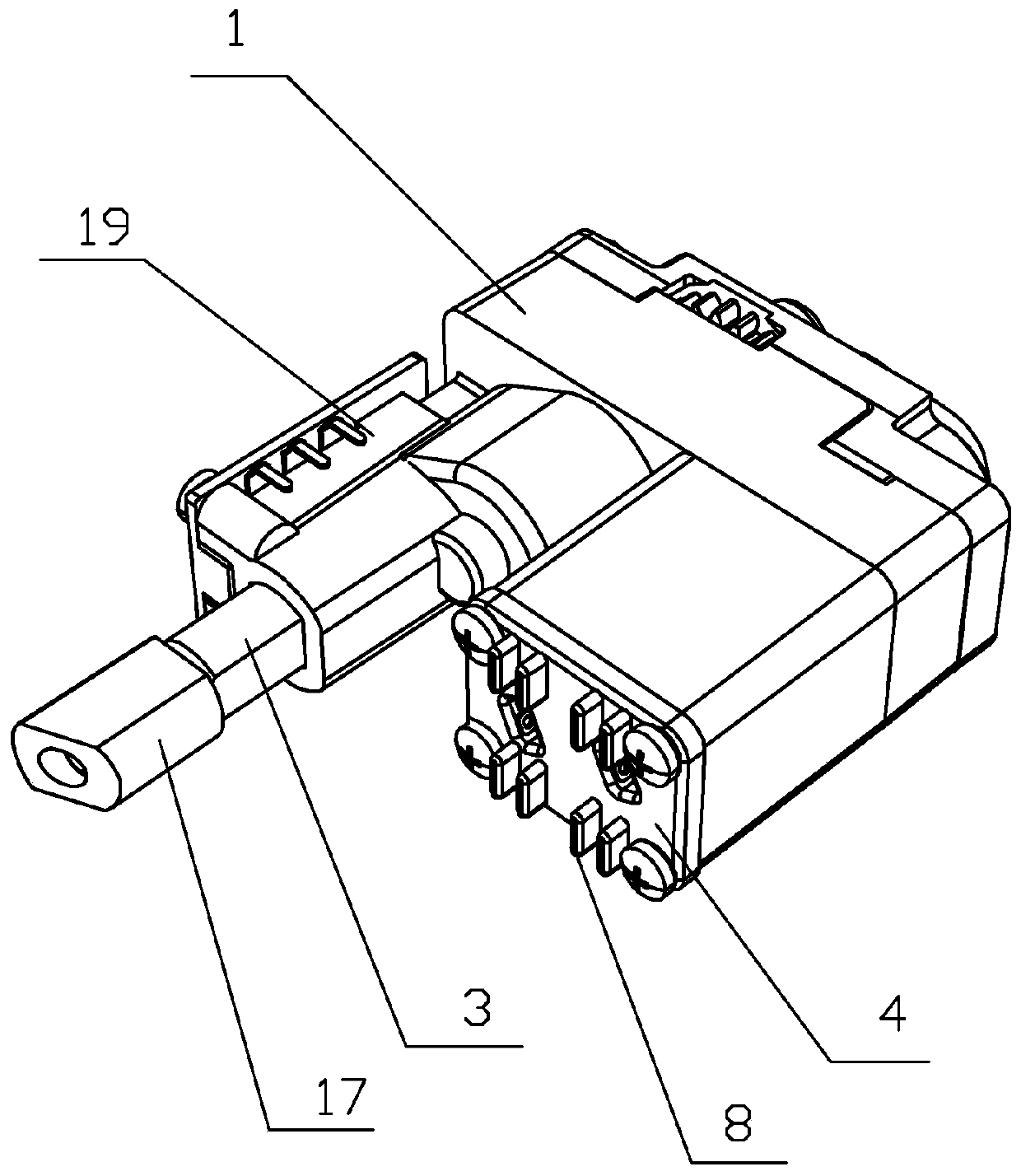
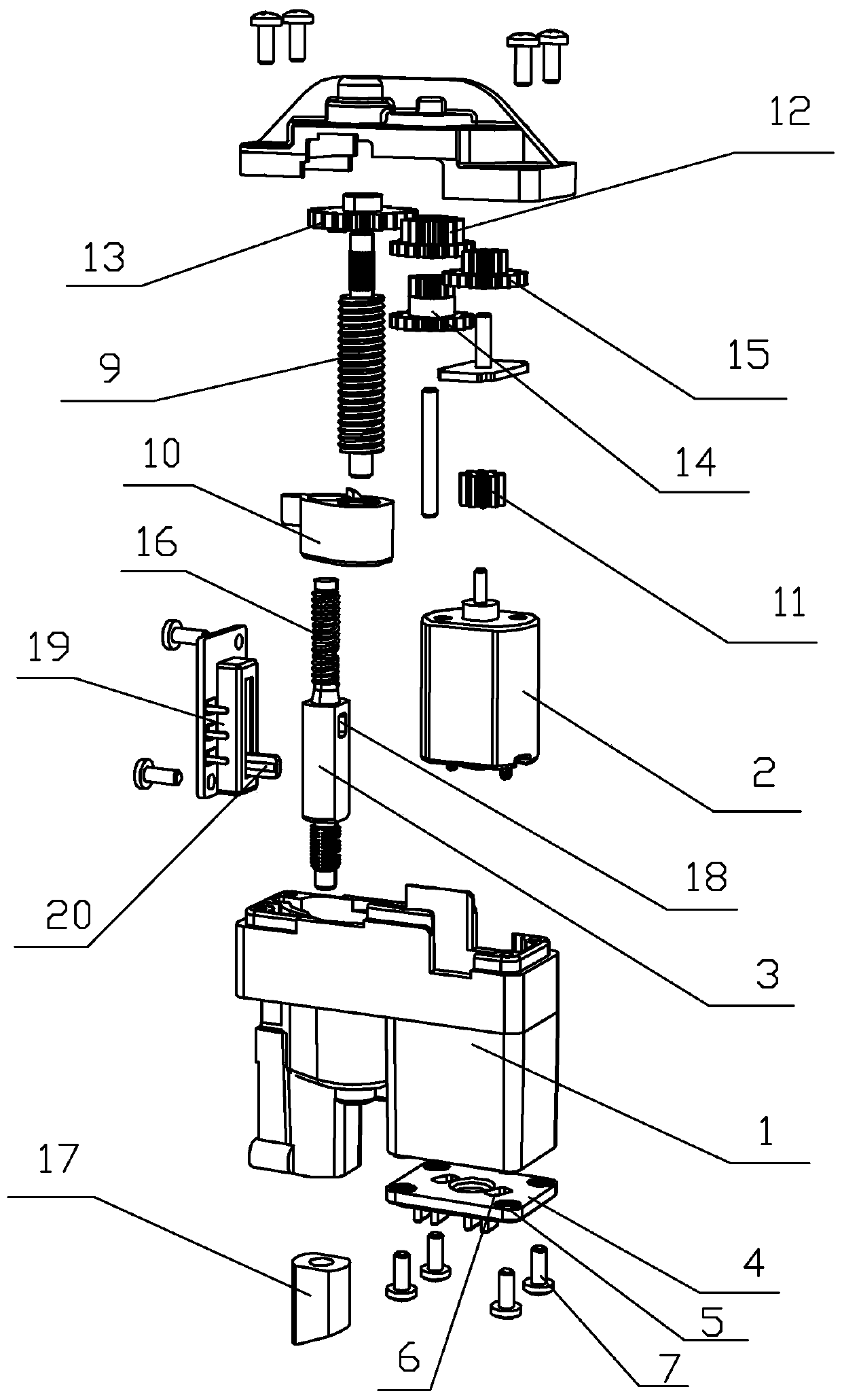
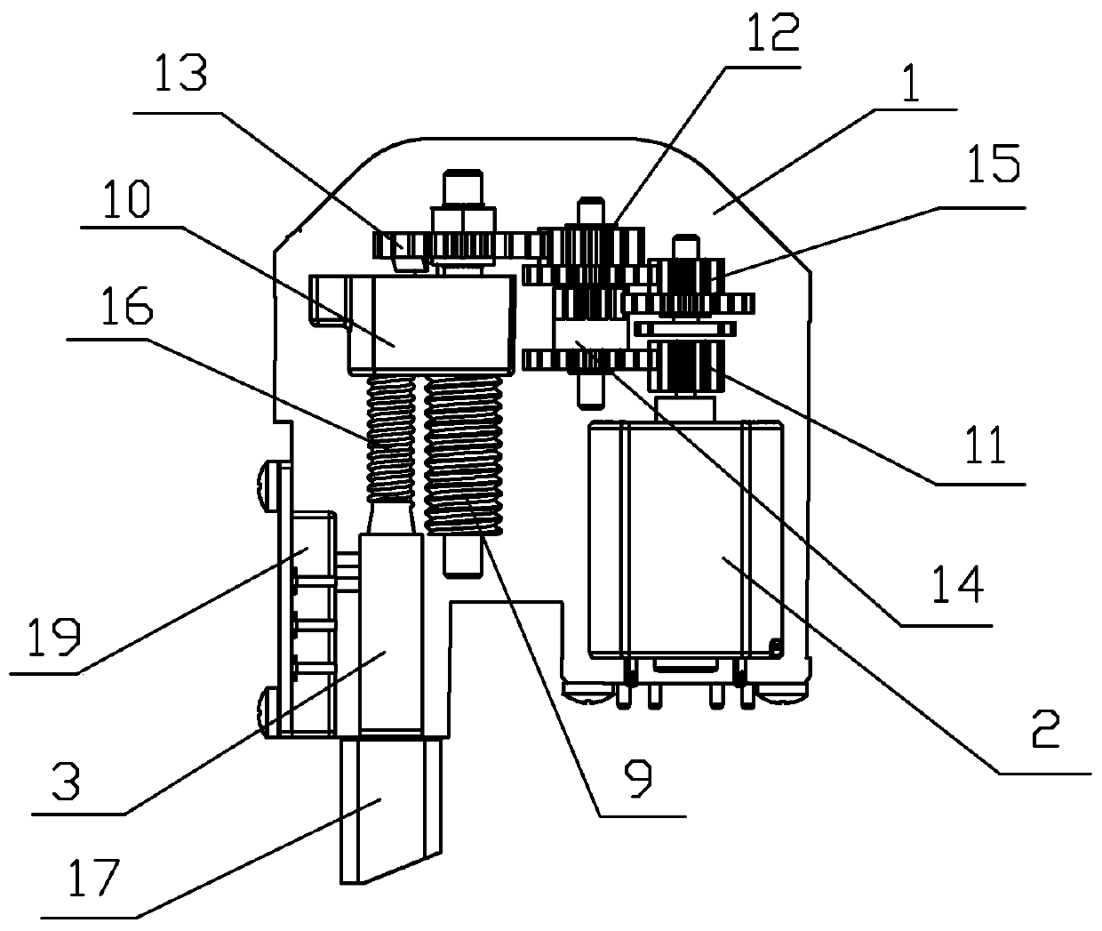
[0021] Embodiment: a kind of lock control device for smart bicycle of this embodiment, such as figure 1 , figure 2 , image 3As shown, it includes a shell 1, which is formed by connecting the left shell, the right shell, and the upper shell. A DC motor 2 is installed in the right shell, a transmission mechanism is installed in the upper shell, and a push rod is installed in the left shell. 3. A motor fastening plate 4 is installed on the bottom of the right housing. There are threaded holes 5 and two through holes 6 matching the DC motor on the motor fastening plate. The two electrodes of the DC motor extend into the two poles respectively. In a through hole, it is convenient to connect the wires, and screws 7 are screwed into the threaded holes to fix the DC motor to the right housing. There are four pairs of positioning blocks 8 protruding from the side of the motor fastening plate away from the DC motor, so that when the device is installed on the car lock, it is clamped...


PUM


Abstract

The invention relates to a lockset control device for an intelligent bicycle. The lockset control device comprises a housing; the housing is provided with a direct current motor, a transmission mechanism and a top rod; the transmission mechanism consists of five gears, a lead screw and a connecting piece; the first gear is arranged at an output shaft of the direct current motor; the gears are engaged; the last one gear is arranged at the top end of the lead screw; the lead screw is in threaded connection with the connecting piece; the top end of the top rod is fixedly connected with the connecting piece; the bottom end of the top rod protrudes out of the housing; a chuck is arranged on the top rod; a toggle switch is arranged on the housing; a clamping hole is formed in the top rod; and ashifting block of the toggle switch is connected with the clamping hole in a clamped manner. The top rod is controlled by the direct current motor to extend and contract vertically, and fits with a lock ring in a bicycle lock of the bicycle to complete locking, unlocking and locking prohibition operation, so that the electronic fence function of the shared bicycle is realized; and a user can complete locking simply after parking the shared bicycle in a specified area, so that a bicycle borrowing flow is finished, the parking position of the shared bicycle is limited, and the shared bicycle isparked orderly and standardly.

Description

technical field [0001] The invention relates to a smart bicycle lock, in particular to a lock control device for a smart bicycle. Background technique [0002] At present, shared bicycles are developing rapidly, which brings convenience to people. At the same time, some behaviors of parking shared bicycles indiscriminately also have a bad impact on the city environment. At present, the smart locks used for bicycles are still unlocked by traditional cam motor modules combined with metal mechanical structures. The key parts of this kind of locks are prone to rust, which affects the smooth completion of unlocking and locking of bicycles, and often needs to be replaced. The operation and maintenance cost of bicycle delivery enterprises. More importantly, due to its structural characteristics, the current smart bicycle lock cannot realize the electronic fence function and cannot limit the parking position of shared bicycles. If the random parking of shared bicycles cannot be gui...

Claims


Application Information

Patent Timeline
Patent Type & Authority Patents(China)
IPC IPC(8): E05B71/00E05B47/00E05B17/20E05B15/00H04W4/44
CPCE05B15/00E05B17/2011E05B47/0012E05B71/00H04W4/44
Inventor 陈秋煌刘涵
Owner 杭州速利科技有限公司
Learn More