
Flowrate regulating device for infusion set

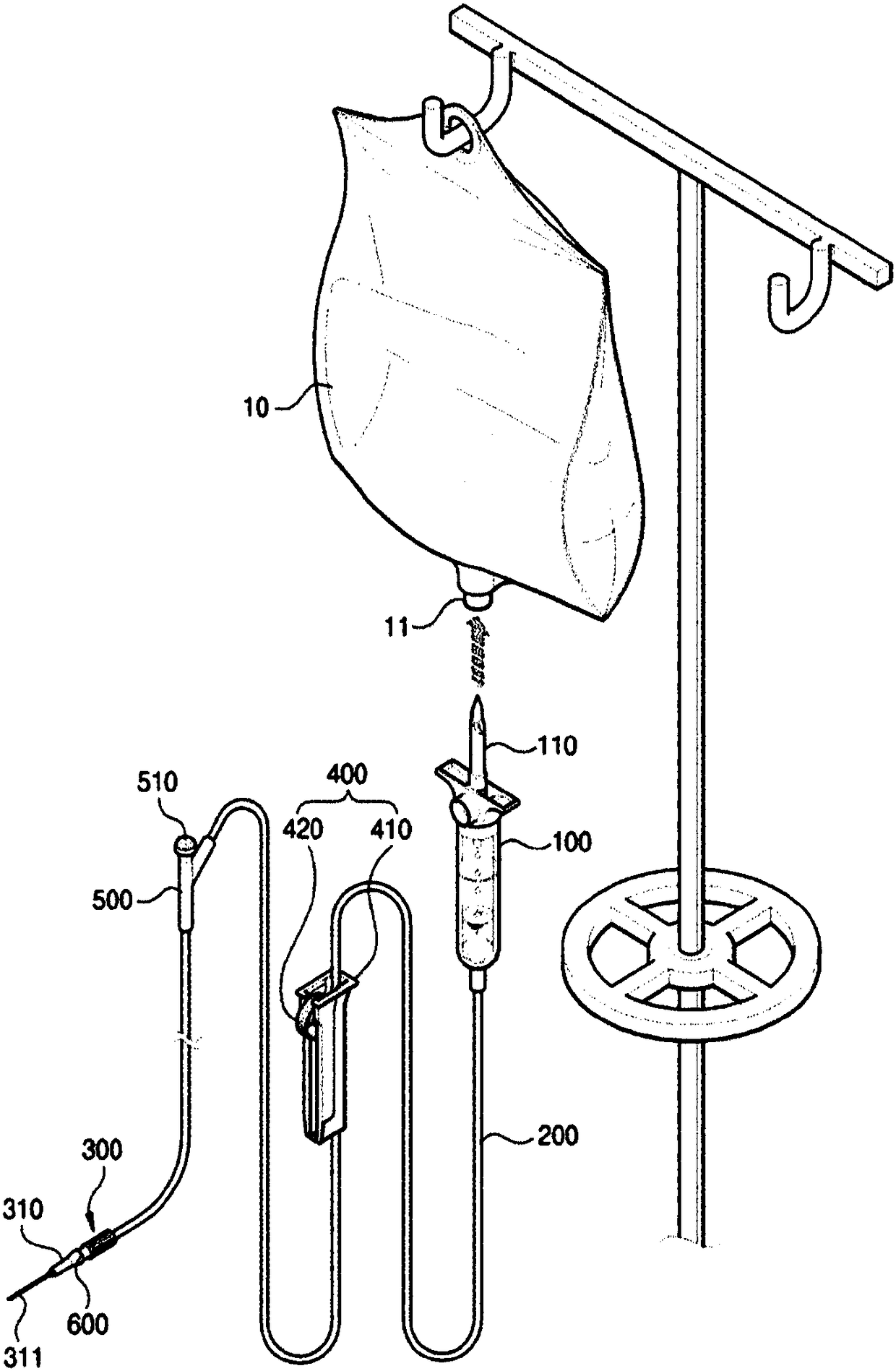
A technology for a flow regulating device and an infusion device, which is applied in the directions of flow control, flow monitor, control/regulation system, etc., can solve the problems of difficult injection molding, complicated infusion moving lines, unsmooth infusion flow, etc., and achieves easy injection molding, The overall structure is simple and the infusion flow is smooth.

Inactive Publication Date: 2018-07-31
李炫禑
View PDF7 Cites 2 Cited by
  • Summary
  • Abstract
  • Description
  • Claims
  • Application Information

AI Technical Summary

Problems solved by technology

[0006] However, the overall structure of the rotary flow regulating device composed of the above structure is very complicated, and it is not easy to be injection molded.

Method used


Image

  • Flowrate regulating device for infusion set
  • Flowrate regulating device for infusion set
  • Flowrate regulating device for infusion set

Examples


Embodiment Construction

[0043] best practice

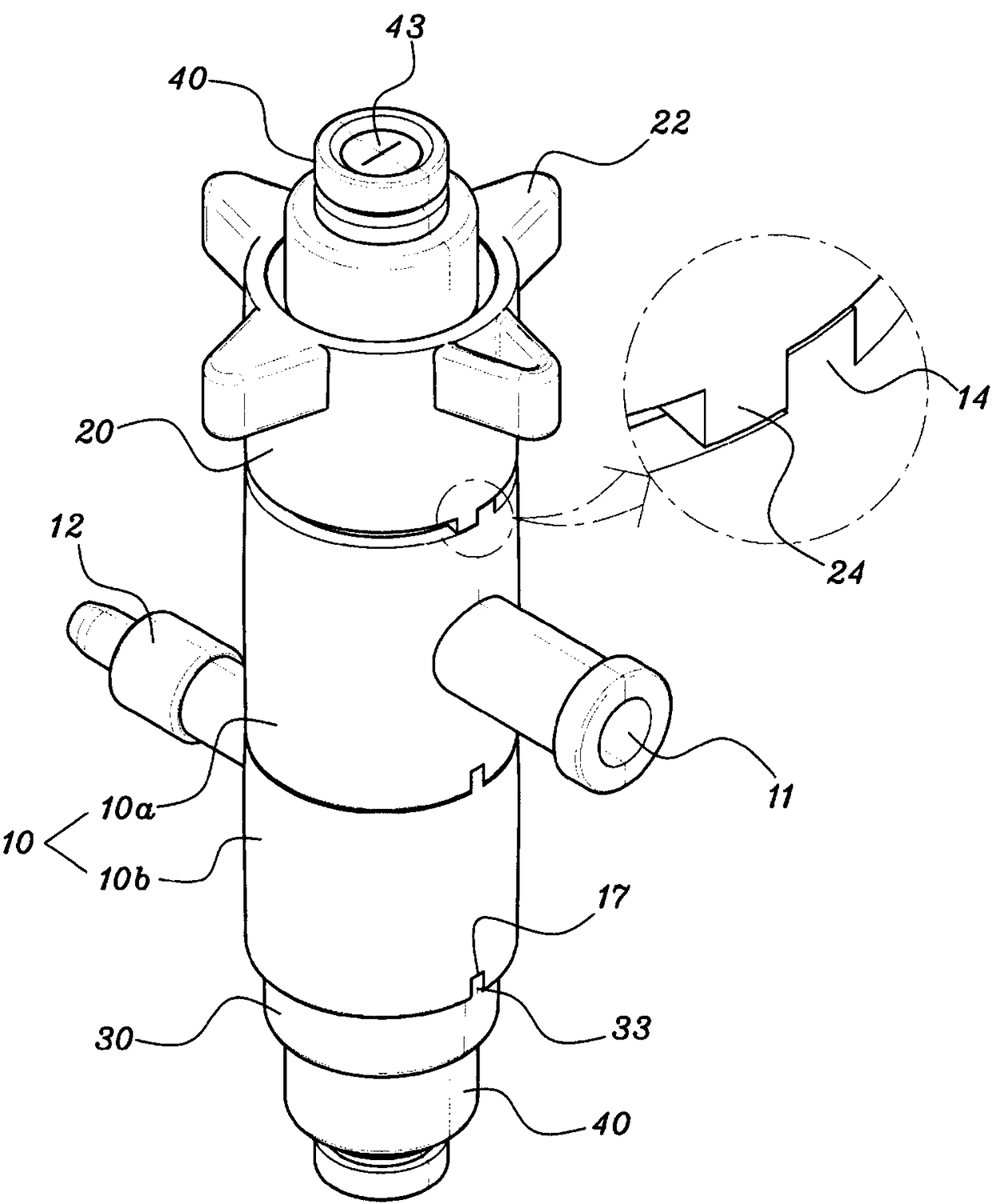
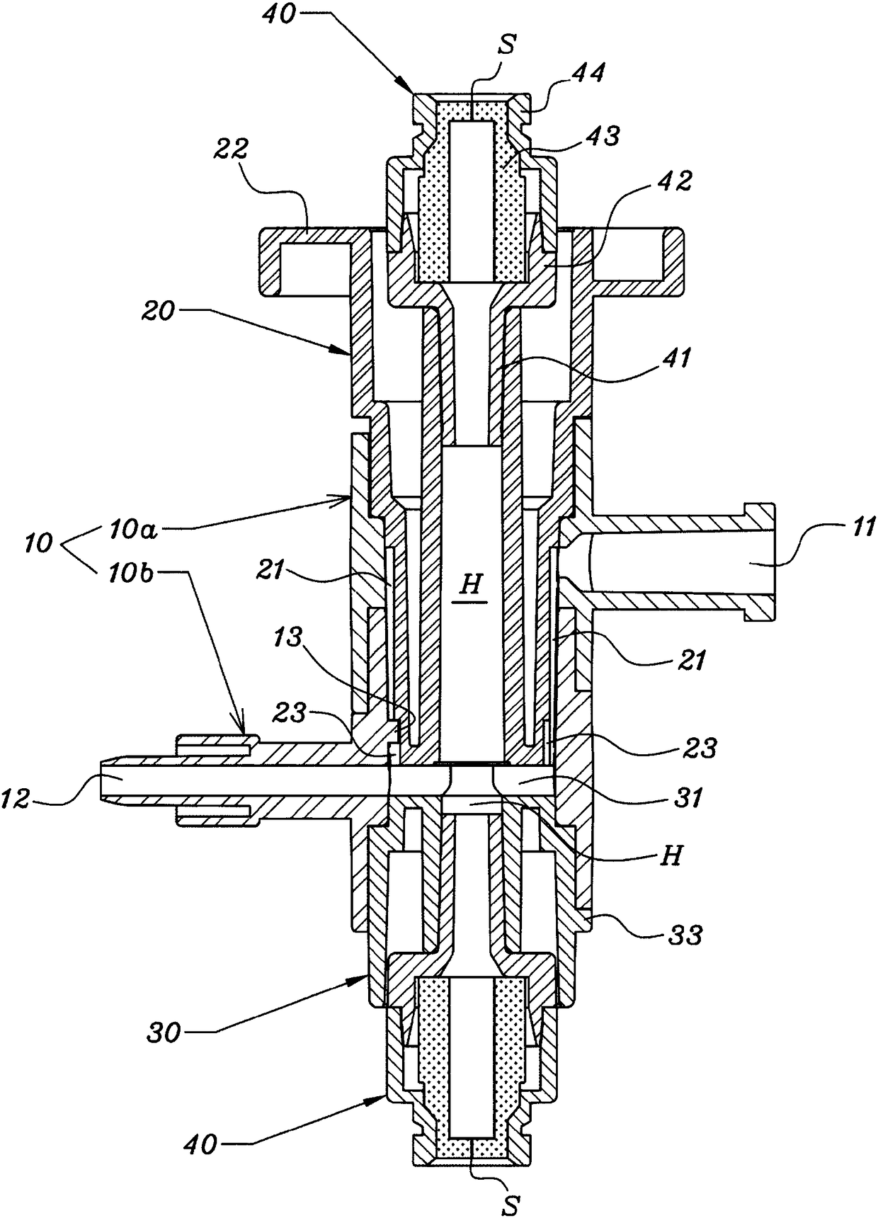
[0044] The present invention is described in detail below in conjunction with accompanying drawing. However, the structures that are necessary for the implementation of the present invention, but belong to the known technology, or the structures that are easily implemented by those skilled in the art according to the known technology will not be described in detail. For convenience, Figure 2 to Figure 4 Among them, referring to the main body part 10, the side where the rotating part 20 is combined is called the "upward" direction, and the side where the fixed part 30 is combined is called the "downward" direction. Members having the same function are given the same reference numerals even if they are provided at mutually different positions.

[0045] The flow regulating device for the infusion device of the present invention is as figure 2 As shown, it includes: a cylindrical main body part 10 open up and down; a rotating part 20 rotatably coupled t...


PUM


Abstract

The present invention relates to a flowrate regulating device for a medical infusion set and, more specifically, to a flowrate regulating device for an infusion set, the device comprising: a body member formed in a cylindrical shape opened vertically, and having an inflow tube and a discharge tube, which protrude from both sides thereof; a rotating member rotatably coupled to the upper end of thebody member, and having a plurality of flowrate regulating passages provided on the outer diametral surface thereof and connected to the inflow tube; a fixing member fixedly coupled to the lower end of the body member, and having a discharge passage provided on the upper surface thereof and connecting the lower ends of the flowrate regulating passages and the discharge tube; and an injection portunit selectively provided at the rotating member and / or the fixing member.

Description

technical field [0001] The present invention relates to a flow regulating device for a medical infusion device, and more specifically, as a flow regulating device for an infusion device, its structure includes: a main body part, which is in the shape of a cylinder open up and down, and an inflow pipe and a discharge pipe protrude from two sides. side; a rotating part, which is rotatably combined with the upper end of the main part, and a plurality of flow adjustment passages joined to the inflow pipe are provided on the outer diameter surface; a fixed part, which is fixedly combined with the lower end of the main part A discharge channel connected between the lower end of the flow regulating channel and the discharge pipe is provided on the upper surface; an injection hole unit is optionally provided on at least one side of the rotating part and the fixed part. Background technique [0002] Infusion devices usually refer to medical appliances used to infuse the human body. ...

Claims


Application Information

Patent Timeline
Patent Type & Authority Applications(China)
IPC IPC(8): A61M5/168
CPCA61M2039/226A61M5/16881A61M2039/229A61M5/16804A61M5/16813A61M39/22
Inventor 李炫禑
Owner 李炫禑
Learn More