Centrifugal clutch

A centrifugal clutch and clutch technology, applied in clutches, automatic clutches, mechanical equipment, etc., can solve the problems of difficult operation by operators, long time, low fuel efficiency, etc., and achieve the effect of simplifying the structure and suppressing vibration.

Inactive Publication Date: 2018-07-31
FCC KK
View PDF7 Cites 4 Cited by
  • Summary
  • Abstract
  • Description
  • Claims
  • Application Information

AI Technical Summary

Problems solved by technology

[0007] However, in the centrifugal clutch disclosed in the aforementioned Patent Document 1, since the clutch weight gradually comes into frictional contact with the clutch cover as the engine speed increases, it takes a long time for the engine speed to increase until the clutch is in a connected state. , while having the problem of fuel consumption with low fuel efficiency
On the other hand, in the centrifugal clutch described in Patent Document 2, since the rotor slips on the cam-shaped protrusion immediately after the cam-shaped protrusion rotates, and the clutch is brought into a connected state, there is a sudden movement of the driven side, causing the operator to elusive problem

Method used


Image

  • Centrifugal clutch
  • Centrifugal clutch
  • Centrifugal clutch

Examples


Embodiment Construction

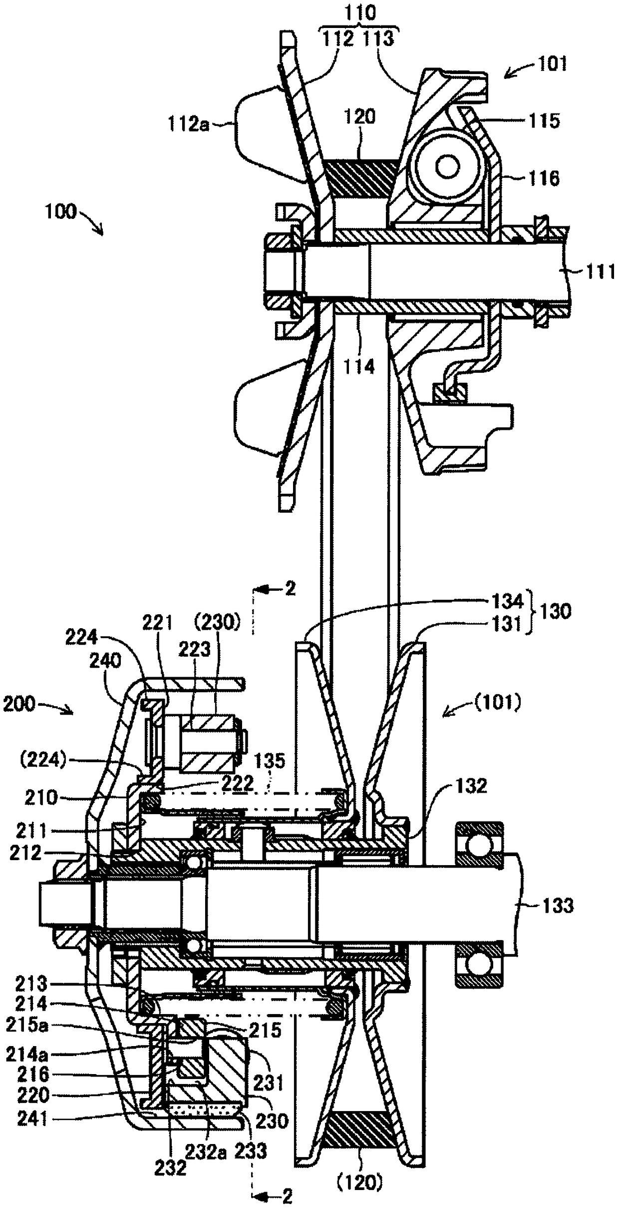
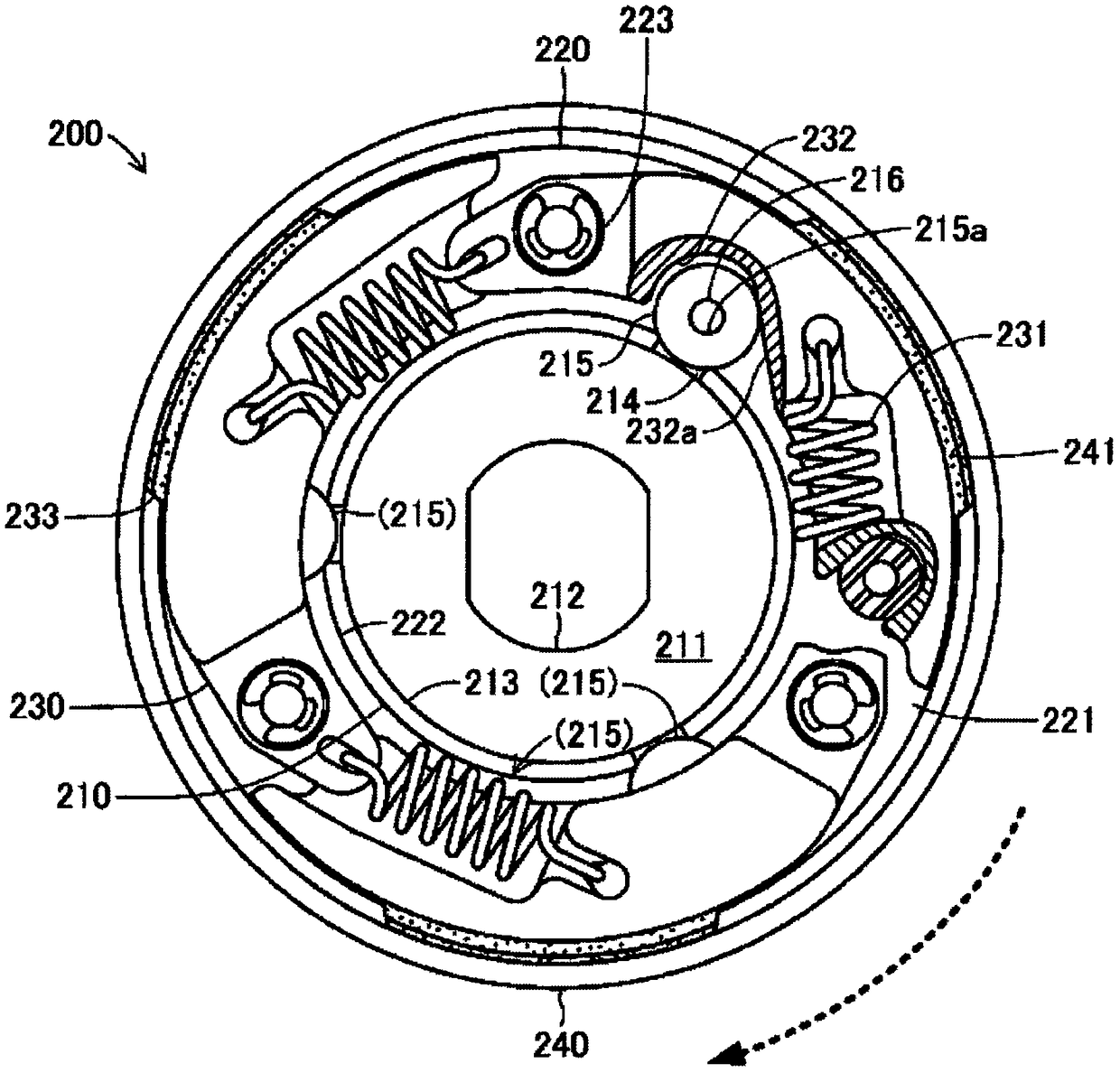
[0035] Hereinafter, one embodiment of the centrifugal clutch according to the present invention will be described with reference to the drawings. figure 1 It is a top sectional view schematically showing the structure of the power transmission mechanism 100 provided with the centrifugal clutch 200 of the present invention. also, figure 2 for from figure 1 A side view of the centrifugal clutch 200 is shown on the 2-2 line. The power transmission mechanism 100 equipped with the centrifugal clutch 200 is mainly installed between the engine and the rear wheel as the driving wheel in a motorcycle such as a scooter, and rotates the drive while automatically changing the reduction ratio relative to the number of revolutions of the engine. Mechanical device that transmits or disconnects force to the rear wheels.

[0036] (Configuration of Centrifugal Clutch 200)

[0037] The power transmission mechanism 100 mainly includes a transmission 101 and a centrifugal clutch 200 . The tr...


PUM


Abstract

Provided is a centrifugal clutch for limiting sudden driven-side initiation while being capable of rapidly establishing an engaged state. The centrifugal clutch 200 is provided with a first drive plate 210 that is directly rotated and driven by the driving force of the engine and a second drive plate 220 that frictionally contacts the first drive plate 210. The first drive plate 210 is provided with overhanging pieces 215 on supports 214 that overhang the second drive plate 220. The second drive plate 220 rotates and is driven integrally with the first drive plate 210 while allowing relative rotational displacement and is provided with clutch weights 230. The overhanging pieces 215 are configured from cylindrical rollers. On the clutch weights 230, follower parts 232, which have a pressingbody 232a that extends at a slant outward and towards the back in the direction in which the first drive plate 210 rotates and is driven and that contacts an overhanging piece 215, are formed.

Description

technical field [0001] The present invention relates to a centrifugal clutch that cuts off the transmission of rotational driving force to the driven side until the engine reaches a predetermined number of rotations, and transmits the rotational driving force to the driven side when the engine reaches a predetermined number of rotations. Background technique [0002] Conventionally, a centrifugal clutch that transmits rotational drive force to the driven side when the engine reaches a predetermined number of revolutions is used in a motorcycle or a harvester. For example, the following Patent Document 1 discloses a centrifugal clutch in which the clutch counterweight gradually displaces toward the side of the clutch housing and makes frictional contact with the increase in the number of revolutions of the engine. In addition, the following Patent Document 2 also discloses a centrifugal clutch through a cylindrical shape. A centrifugal clutch in which the rotor slides on a ca...

Claims


Application Information

Patent Timeline
IPC IPC(8): F16D43/18
CPCF16D43/18F16D2043/145
Inventor 青野薰木根悠太横道友太片冈真
Owner FCC KK
Why Eureka
Try Eureka