Full-automatic system for stamping sheet metal

A fully automatic, metal sheet technology, applied in the field of metal sheet stamping, can solve the problems of hand squeeze, no height adjustment mechanism, high labor occupation, etc., to achieve the effect of ensuring stability and convenient use

Pending Publication Date: 2018-08-03
青岛创高世纪信息科技有限公司
View PDF11 Cites 9 Cited by
  • Summary
  • Abstract
  • Description
  • Claims
  • Application Information

AI Technical Summary

Problems solved by technology

[0002] According to the actual situation, the metal sheet needs to be processed into a shape suitable for current use by a stamping device. The existing stamping device has the following problems when stamping the metal sheet with different shapes or patterns; the feeding device on the existing stamping device does not have Height adjustment mechanism, which requires manually aligning the height of the feeding device with the height of the punching machine, and cannot guarantee the stability during the working process, and the feeding device is not easy to clamp the metal sheet, which often occurs during the transportation process, and the metal sheet The falling situation affects the work efficiency. There is also a traditional way to manually remove the metal sheet processed on the punching machine, but this method is easy to squeeze the hands of the human body, and the second is low work efficiency and takes up labor. High, unable to meet the needs of modern processing

Method used


Image

  • Full-automatic system for stamping sheet metal
  • Full-automatic system for stamping sheet metal
  • Full-automatic system for stamping sheet metal

Examples


Embodiment Construction

[0034]Embodiments of the technical solutions of the present invention will be described in detail below in conjunction with the accompanying drawings. The following examples are only used to illustrate the technical solutions of the present invention more clearly, and therefore are only examples, rather than limiting the protection scope of the present invention.

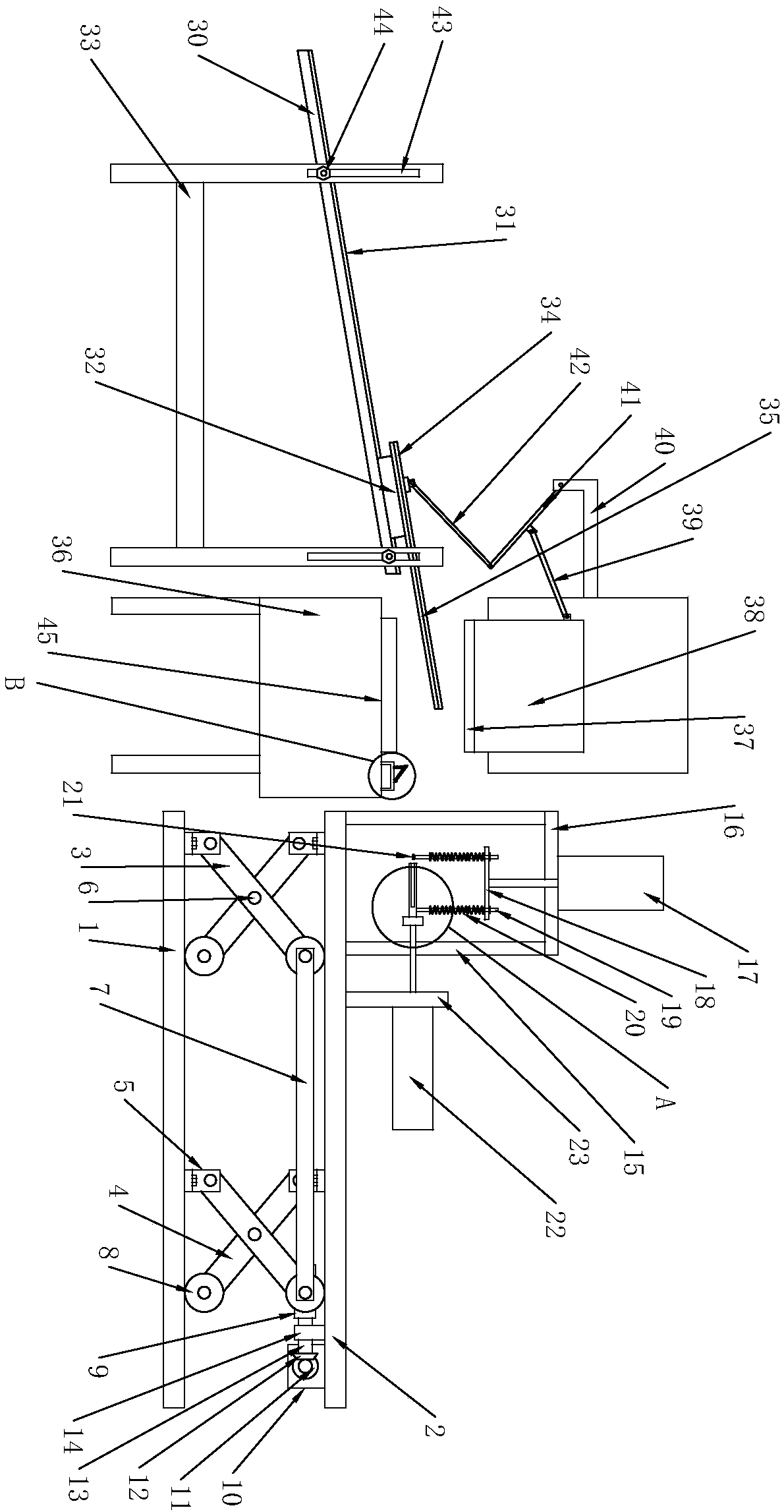
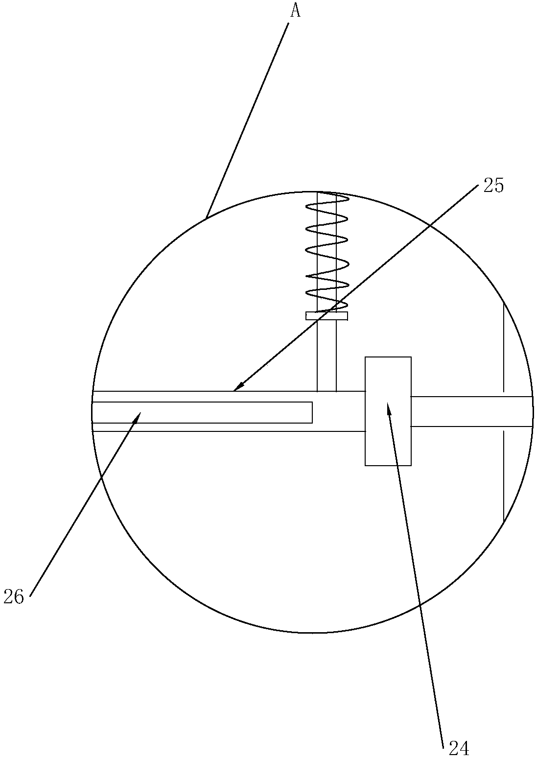
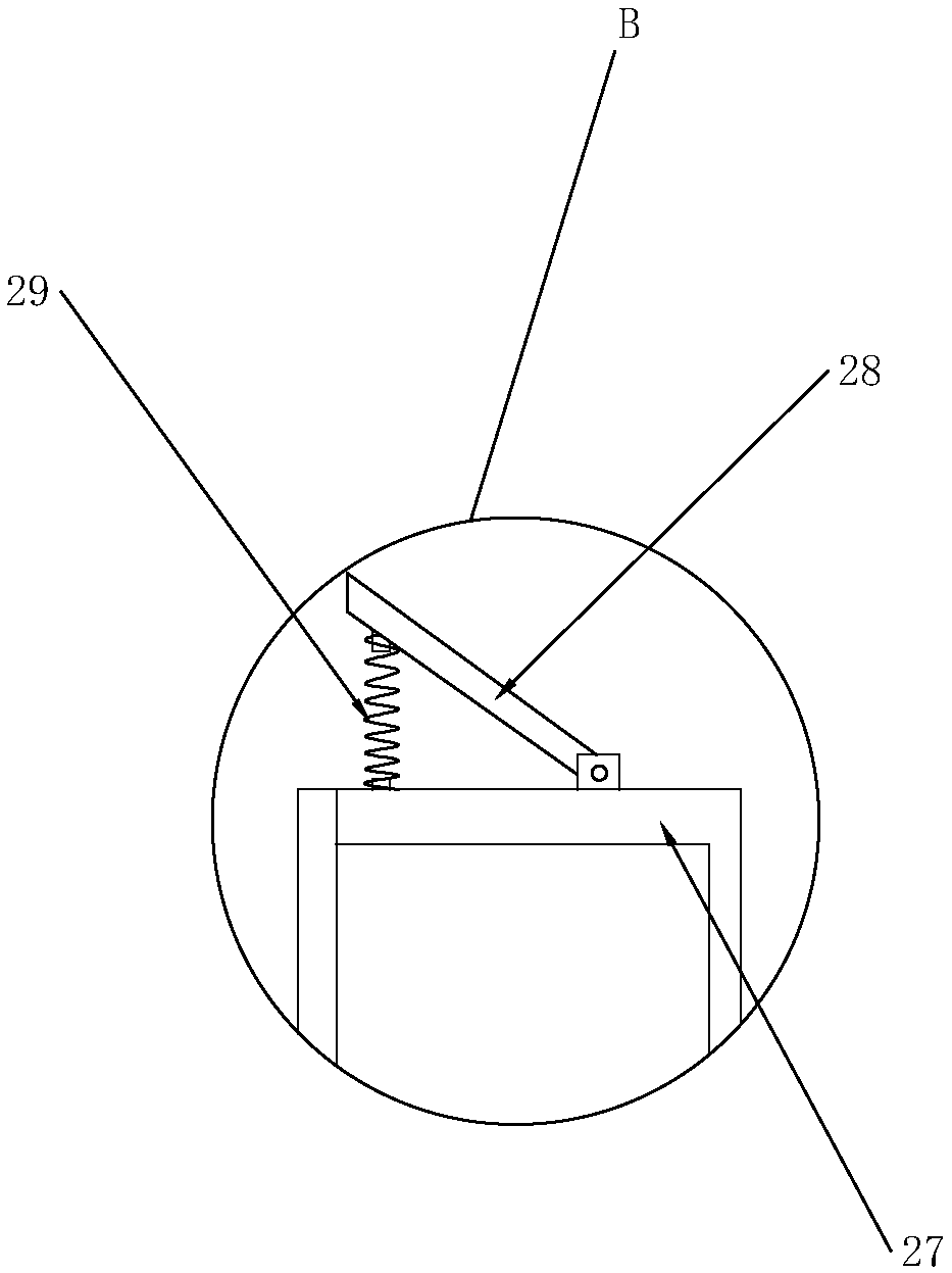
[0035] Such as Figure 1 to Figure 3 As shown, the fully automatic system for sheet metal stamping includes a base 1, a support plate 2, a mounting frame, a feeding plate 30, a mounting seat 32, and a punching machine body 36; the base 1 and the support plate 2 are arranged horizontally up and down, and pass A lift space is formed between the base 1 and the support plate 2. Two sets of support frames are arranged side by side in the lift space, and each set of support frames includes two lift frames arranged side by side. The arrangement of the lift frames is perpendicular to the arrangement of the support frames. ...


PUM


Abstract

The invention discloses a full-automatic system for stamping sheet metal, and relates to the technical field of sheet metal stamping. The full-automatic system comprises a base, a supporting plate, amounting frame, a material conveying plate and a punching machine body; the base and the supporting plate are arranged horizontally up and down correspondingly, two groups of supporting frames are arranged in parallel in a lifting space, and each group of supporting frames comprises two lifting frames arranged in parallel, wherein each lifting frame comprises a first supporting rod and a second supporting rod; the supporting plate is further provided with a clamping mechanism in a sliding mode up and down, a feeding mechanism is horizontally arranged on one side of the clamping mechanism in asliding mode, and the punching machine body is positioned at the limit position where the feeding mechanism advances; a material returning mechanism is arranged on a supporting platform, in a punchingarea, of the punching machine body; and the material conveying plate is obliquely arranged on the mounting frame. The full-automatic system realizes the technical effects of integrating of feeding, punching and discharging and saving labor force.

Description

technical field [0001] The invention relates to the technical field of sheet metal punching, in particular to a fully automatic system for sheet metal punching. Background technique [0002] According to the actual situation, the metal sheet needs to be processed into a shape suitable for current use by a stamping device. The existing stamping device has the following problems when stamping the metal sheet with different shapes or patterns; the feeding device on the existing stamping device does not have Height adjustment mechanism, which requires manually aligning the height of the feeding device with the height of the punching machine, and cannot guarantee the stability during the working process, and the feeding device is not easy to clamp the metal sheet, which often occurs during the transportation process, and the metal sheet The falling situation affects the work efficiency. There is also a traditional way to manually remove the metal sheet processed on the punching m...

Claims


Application Information

Patent Timeline
Patent Type & Authority Applications(China)
IPC IPC(8): B21D43/02B21D43/18B21D43/13B21D45/02B21D22/02
CPCB21D22/02B21D43/026B21D43/027B21D43/13B21D43/18B21D45/02
Inventor 宋建雷
Owner 青岛创高世纪信息科技有限公司
Why Eureka
Try Eureka