Connection structure of balance car frame

A technology of connecting structure and balancing scooter, applied in the field of balancing scooters, can solve the problems of incapability of balancing scooters, high production cost, inconvenient installation, etc., and achieve the effect of avoiding acceleration or deceleration too fast, reducing production cost, and facilitating installation and production.

Inactive Publication Date: 2018-08-03
吕林宝
View PDF8 Cites 6 Cited by
  • Summary
  • Abstract
  • Description
  • Claims
  • Application Information

AI Technical Summary

Problems solved by technology

[0003] But the two-wheel balance car on the market still has deficiencies. There are two kinds of balance cars with integrated frame and left and right side pedals on the market that can rotate relatively. Apply for an adjustment mechanism of a balance car and a balance car. The balance car controls and adjusts the moving direction and speed of the balance car through an induction adjustment component. However, it is difficult for the user to maintain the same force on the two pedals when using the balance car. Moving forward in a straight line, the user needs to always pay attention to the movement direction of the balance car and adjust the movement direction of the balance car, which is inconvenient for users to use; most balance cars on the market with left and right pedals that can rotate relative to each other have two pedals that are hinged at the connecting position , such as the application number CN201620233802.1 application balance car, because the two-wheel balance car is supported by the wheels on both sides, and the two pedals are connected by direct hinges, it is not easy to install, the stress is concentrated at the hinged position of the pedals, and the use of high strength is required The production cost is high, and after the user uses it for a long time, the joint between the two pedals is prone to deformation, and the relative rotation of the pedals is easily affected, which affects the normal use of the balance bike

Method used


Image

  • Connection structure of balance car frame
  • Connection structure of balance car frame
  • Connection structure of balance car frame

Examples


Embodiment Construction

[0027] The present invention will be further described below in conjunction with accompanying drawing with specific embodiment:

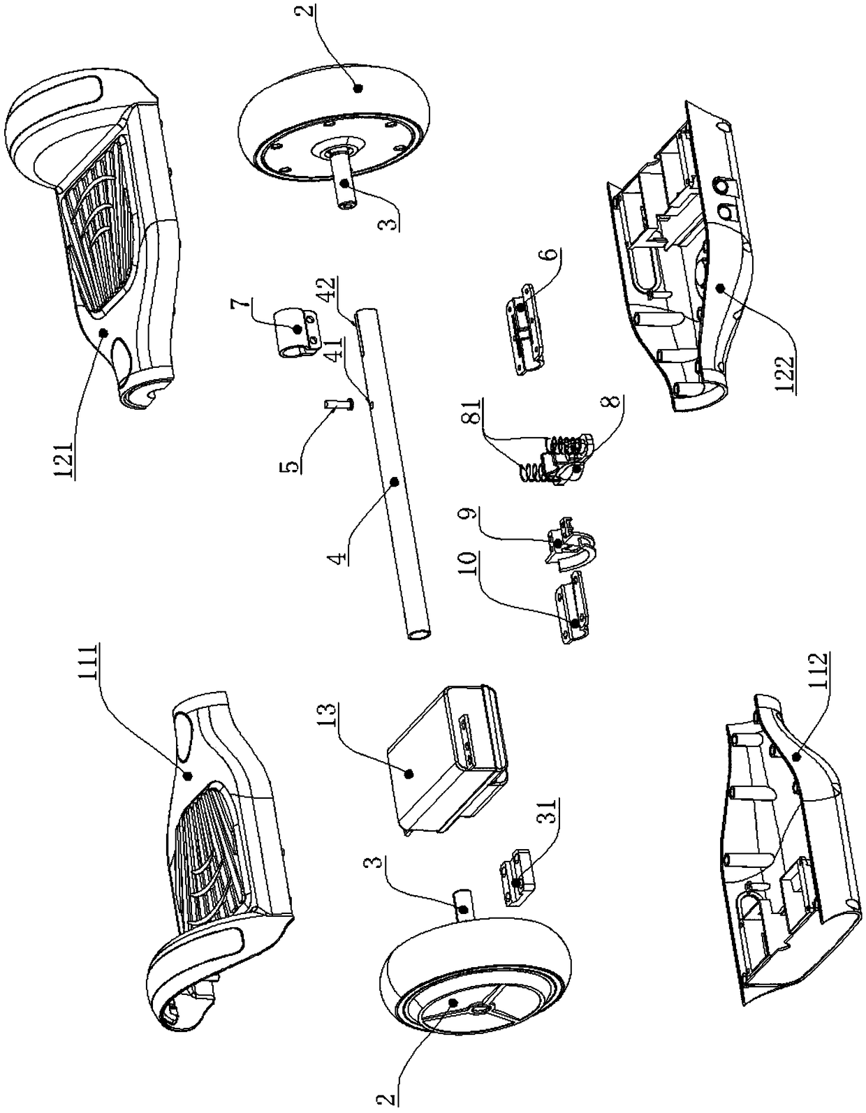
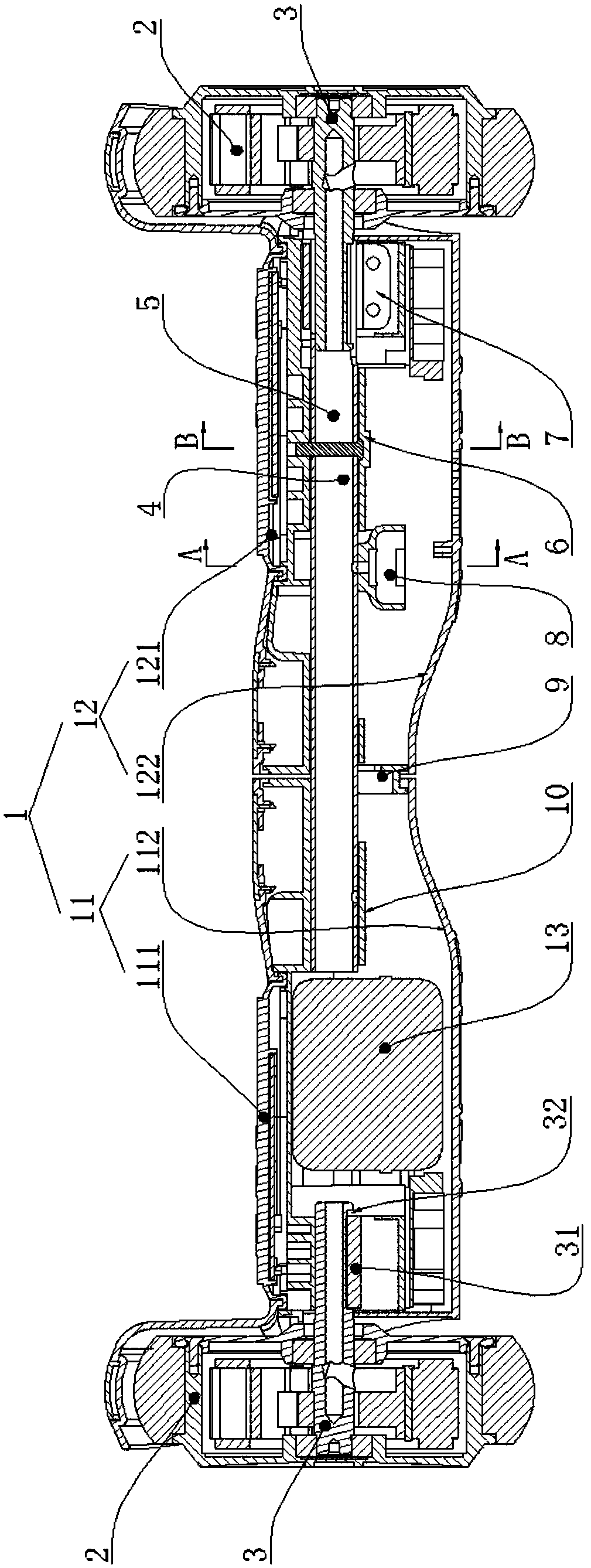
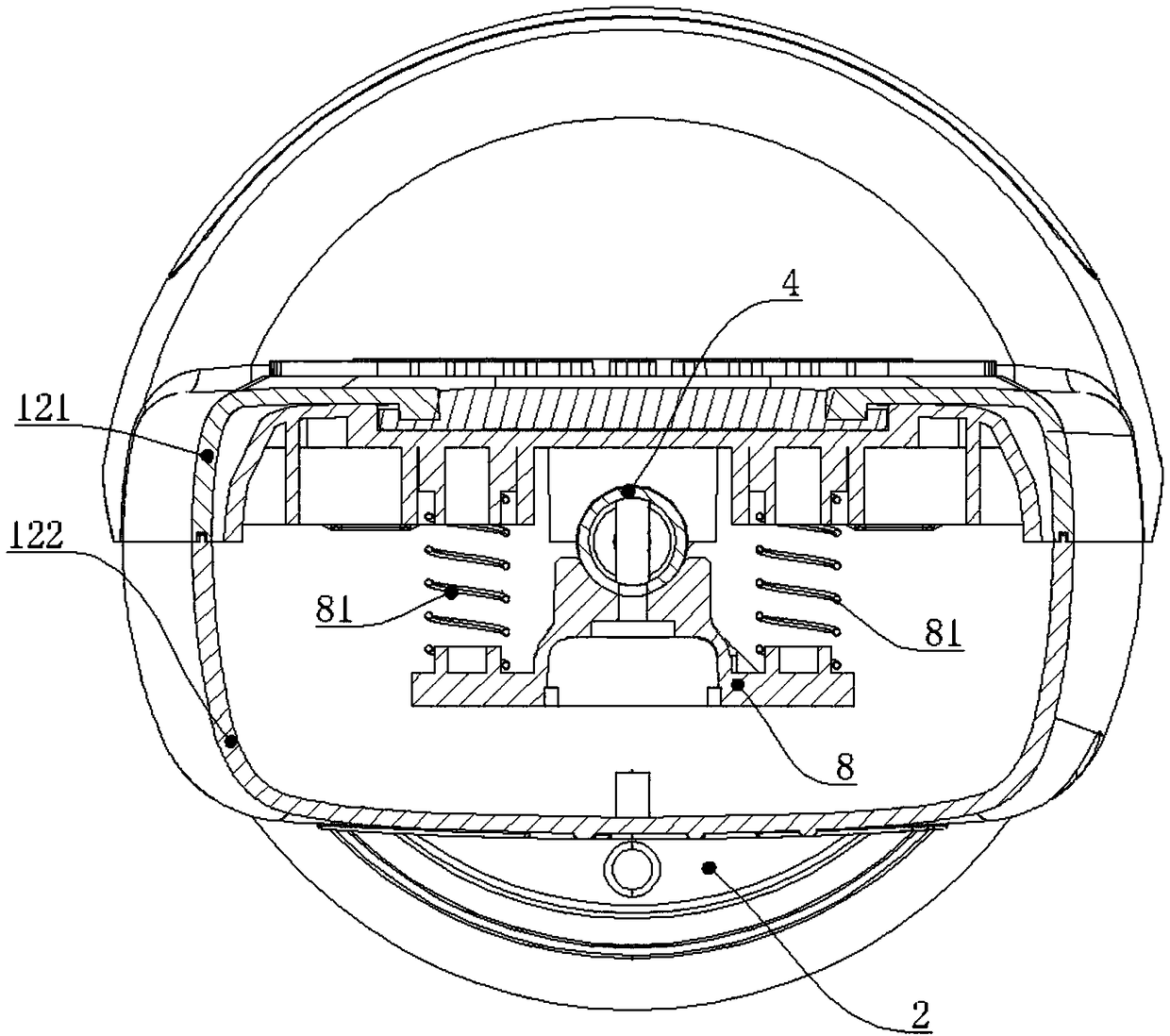
[0028] See Figure 1 to Figure 5 As shown, a connection structure of a balance car frame includes a frame 1 and two wheels 2 respectively arranged on both sides of the frame 1, and a controller and a battery pack 13 for controlling the automatic balance of the frame are arranged in the frame 1 , the wheel 2 is provided with a hub motor, and the hub motor in the wheel 2 is convenient for the independent movement of the two wheels 2, which is convenient for the flexible control of the balance car. The hub motor is provided with a rotating shaft 3, and the wheel 2 is connected to the frame 1 through the rotating shaft 3. Vehicle frame 1 comprises left pedal 11 and right pedal 12, described vehicle frame 1 is provided with connecting rod 4, the left side of connecting rod 4 is fixedly arranged on the right side of left pedal 11, and right pedal 12 is co...


PUM


Abstract

The invention belongs to the technical field of balance cars and particularly relates to a connection structure of a balance car frame. The connection structure includes a car frame body and two wheels which are arranged on both sides of a car body respectively; a controller capable of controlling the car body to stay in balance automatically is arranged in the car frame body, a hub motor is arranged in each wheel, a rotating shaft is arranged in each hub motor, and the car frame body comprises a left pedal and a right pedal; a connecting rod is arranged in the car frame body, the left side ofthe connecting rod is fixed to the right side of the left pedal, the right pedal is rotatably connected with the connecting rod, a rotating shaft of the left wheel is fixedly arranged on the left pedal, and the right wheel is fixedly arranged on the right side of the connecting rod. The connection structure of the balance car frame aims at achieving the effects that installation is convenient andsteering is flexible.

Description

technical field [0001] The invention belongs to the technical field of self-balancing vehicles, and in particular relates to a connection structure of a vehicle frame of a self-balancing vehicle. Background technique [0002] With the continuous improvement of people's living standards, people pay more and more attention to improving the quality of life. Fitness, leisure, and entertainment have become an indispensable part of people's lives. Various forms of fitness and entertainment equipment emerge in endlessly. In the trend of people traveling instead, the balance bike has won everyone's love through its small size, beautiful appearance and flexible operation. At present, there are two types of self-balancing vehicles on the market: one-wheeled and two-wheeled. Among them, the two-wheeled self-balancing vehicle has a higher safety factor and is more suitable for transportation. [0003] But the two-wheel balance car on the market still has deficiencies. There are two kin...

Claims


Application Information

Patent Timeline
Patent Type & Authority Applications(China)
IPC IPC(8): B62K11/00
CPCB62K11/007
Inventor 吕林宝吕永剑
Owner 吕林宝
Why Eureka
Try Eureka