Crankset, auxiliary wheel, flywheel and anti-off chain transmission device
A technology of crankset and chain, applied in chain/belt drive, transportation and packaging, vehicle gearbox, etc., can solve the problems of difficult maintenance and poor user experience, and achieve the effect of improving the difficulty of disassembly
- Summary
- Abstract
- Description
- Claims
- Application Information
AI Technical Summary
Problems solved by technology
Method used
Image
Examples
Embodiment 1
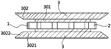
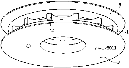
[0040] like Figure 1-2 As shown, a crankset (1) of the present invention includes a crankset body (2) and a baffle (3). There are two baffle plates (3), which are respectively fixed on the two sides of the chainring body (2). The baffle (3) includes a fixing part (301) and an anti-off part (302). The anti-off part (302) includes a limiting part (3021) and a deflection preventing part (3022). The fixing part (301) is arranged parallel to the side wall of the crank body (2) and fixed on the side wall of the crank body (2) in an annular structure or symmetrically arranged legs.
[0041] The limiting part (3021) is an annular structure located on the outer edge of the fixing part (301). The inner ring of the limiting part (3021) is fixedly connected to the outer end of the fixing part (301), and is arranged parallel to and spaced apart from the crankset body (2). The distance between the limiting portion (3021) and the chainring body (2) is smaller than the width of the chain...
Embodiment 2
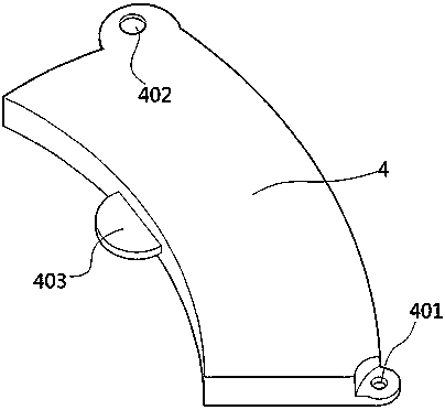
[0045] like Figure 3-9 As shown, a crankset (1) of this embodiment has basically the same main structure as that of Embodiment 1, the difference is that it also includes a maintenance plate (4). One of the two baffles (3) is provided with a cutout (303). The cutout (303) is located on the anti-off portion (302). The cutout (303) allows the chain not engaged with the chainring body (2) to pass through. The slit (303) is provided with a baffle shaft hole (304) near one side edge; a threaded hole (305) is provided near the opposite side edge; and the fixing part (301) is provided with card slot (306). The maintenance plate (4) is adapted to the notch (303), and the maintenance plate (4) is corresponding to the baffle shaft hole (304), threaded hole (305) and card slot (306) on the baffle plate (3). At the position, a maintenance plate shaft hole (401), a through hole (402) and a clamping foot (403) are respectively arranged.
[0046]In this embodiment, when the shaft hole (...
Embodiment 3
[0050] A tooth plate (1) of this embodiment, the main structure is basically the same as that of Embodiment 2, the difference is that: the maintenance plate (4) is a sheet structure adapted to the cutout (303), and the maintenance plate (4) A connecting piece protruding from the side wall is arranged on the edge; a through hole is arranged on the connecting piece. Correspondingly, threaded holes are provided on the baffle (3) corresponding to the through holes on the sheet structure; the maintenance plate (4) is fixed on the baffle (3) by screws.
PUM
 Abstract
Description
Claims
Application Information
 - R&D
- Intellectual Property
- Life Sciences
- Materials
- Tech Scout
- Unparalleled Data Quality
- Higher Quality Content
- 60% Fewer Hallucinations
Browse by: Latest US Patents, China's latest patents, Technical Efficacy Thesaurus, Application Domain, Technology Topic, Popular Technical Reports.
© 2025 PatSnap. All rights reserved.Legal|Privacy policy|Modern Slavery Act Transparency Statement|Sitemap|About US| Contact US: help@patsnap.com


