Geotechnical cloth laying machine used for concrete road

A technology of concrete roads and geotextiles, which is applied in the direction of roads, roads, road repairs, etc., can solve the problems of low laying efficiency, increased labor burden on workers, and time-consuming and laborious laying process, so as to reduce labor burden, improve laying efficiency, and reduce laying costs. The effect of the steps

Inactive Publication Date: 2018-08-03
毕金鹤
View PDF5 Cites 5 Cited by
  • Summary
  • Abstract
  • Description
  • Claims
  • Application Information

AI Technical Summary

Problems solved by technology

[0004] The present invention overcomes that the laying of geotextiles on concrete pavements is generally done manually. Workers transport the geotextiles to the concrete road, and while pushing the geotextile rolls, they fit the geotextiles to the concrete pavement. The laying process is time-consuming and labo

Method used


Image

  • Geotechnical cloth laying machine used for concrete road
  • Geotechnical cloth laying machine used for concrete road
  • Geotechnical cloth laying machine used for concrete road

Examples


Example Embodiment

[0037] Example 1

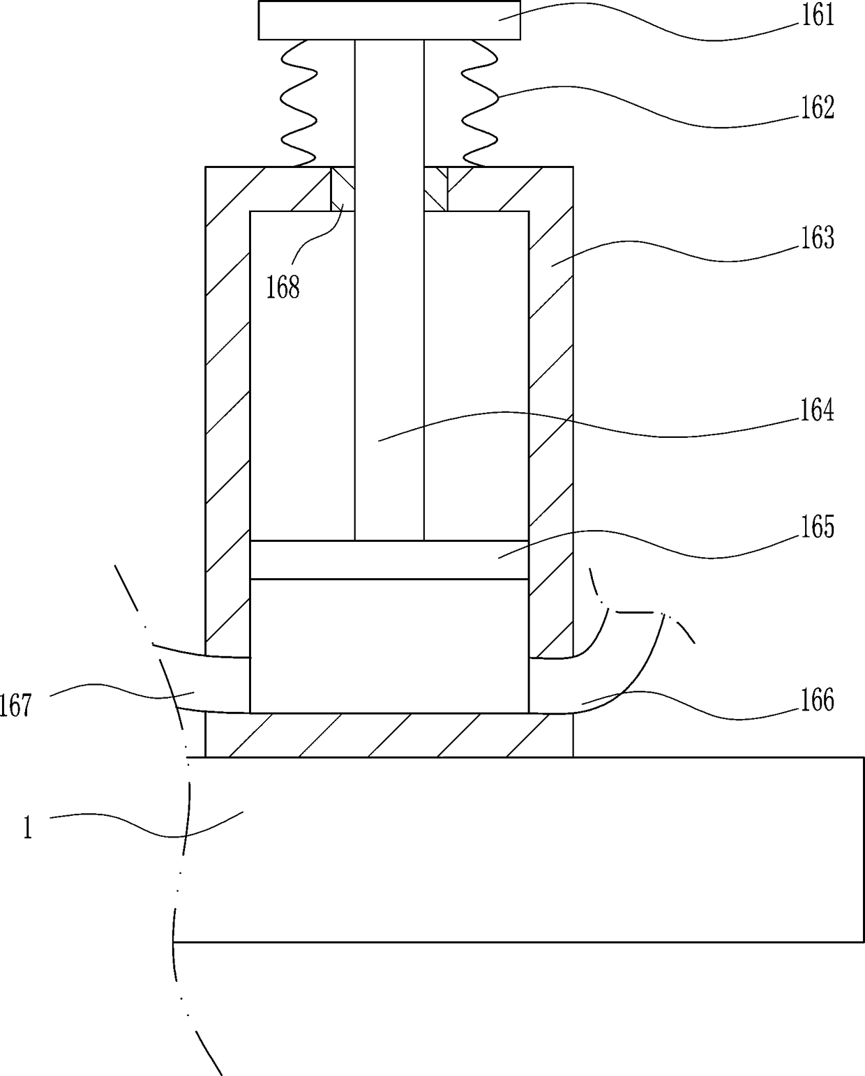
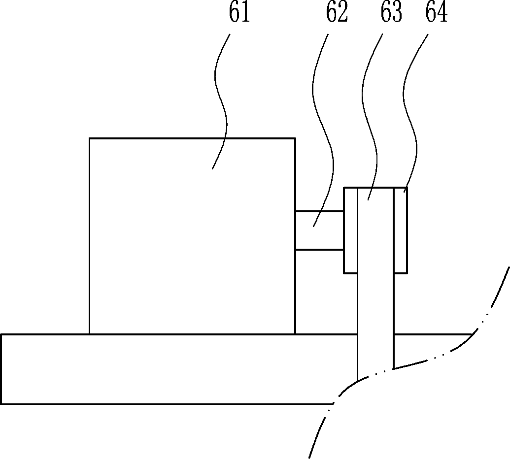
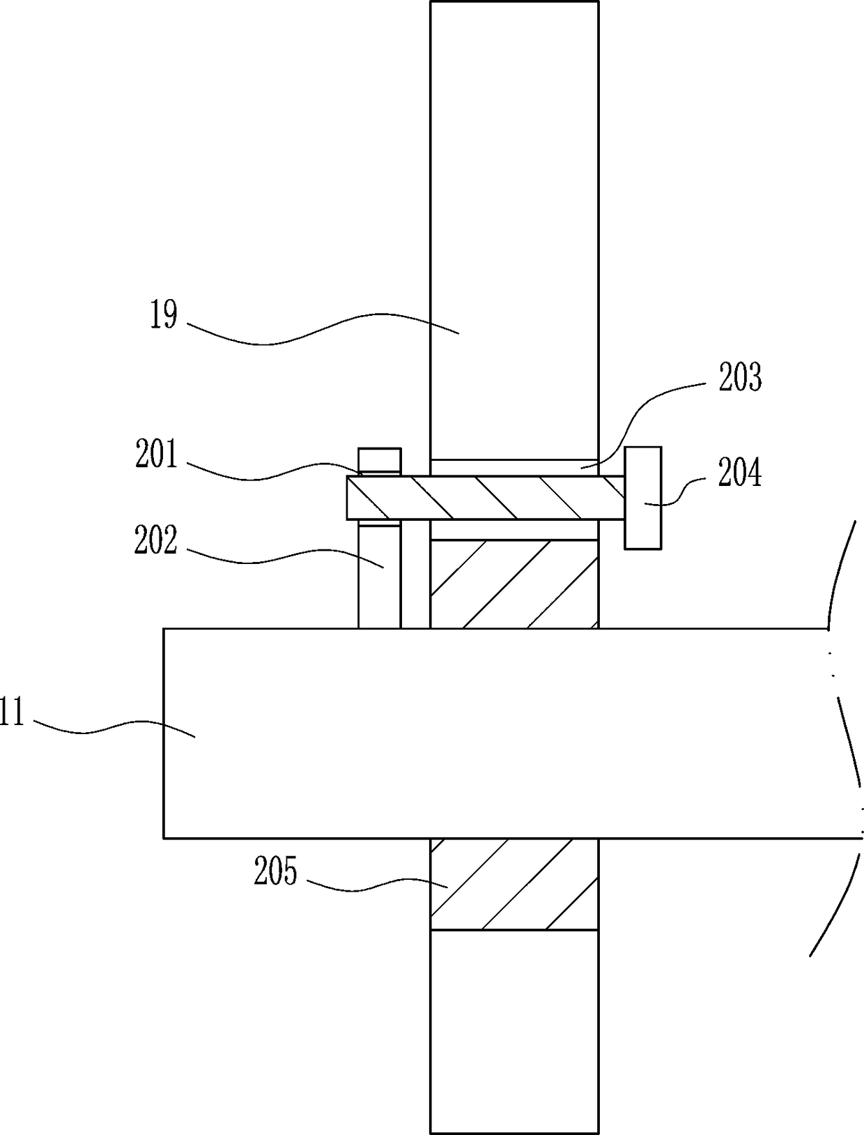
[0038] A geotextile laying machine for concrete roads, such as Figure 1-10 As shown, it includes a bottom plate 1, a wheel 2, a first bearing seat 3, a first pulley 4, a first rotating shaft 5, a driving mechanism 6, a second pulley 7, a first flat belt 8, a third pulley 9, and a second bearing Seat 10, second rotating shaft 11 and first support rod 12; first bearing seat 3 is fixedly connected to the bottom of bottom plate 1, first rotating shaft 5 is pivotally connected to first bearing seat 3, and wheel 2 is fixedly connected to both ends of first rotating shaft 5 The first pulley 4 and the second pulley 7 are affixed to the first rotating shaft 5; the drive mechanism 6 is affixed to one side of the bottom plate 1, and the first support rod 12 is affixed to the other side of the bottom plate 1; the drive mechanism 6 The output end is in transmission connection with the first pulley 4, the second bearing seat 10 is fixedly connected to the top of the fir...


PUM


Abstract

The invention relates to a geotechnical cloth laying machine used for concrete road. The invention provides the geotechnical cloth laying machine used for concrete road, which is capable of mitigatingworker labor burden and increasing the geotechnical cloth laying efficiency. The geotechnical cloth laying machine comprises a base plate, wheels, a first bearing pedestal, a first belt pulley, a first rotating shaft, a driving mechanism, a second belt pulley, a first flat belt, a third belt pulley, a second bearing pedestal, a second rotating shaft, and a first support bar; the first bearing pedestal is fixedly at the bottom of the base plate, the first rotating shaft is subjected to pin joint with the first bearing pedestal, and the wheels are fixedly at two ends of the first rotating shaft. The geotechnical cloth laying machine is capable of mitigating worker labor burden and increasing the geotechnical cloth laying efficiency.

Description

technical field [0001] The invention relates to a geotextile laying machine for concrete roads, in particular to a geotextile laying machine for concrete roads. Background technique [0002] When the concrete road is poured, a layer of geotextile needs to be laid on it to reduce the evaporation of moisture in the concrete and prevent the concrete from cracking. However, the laying of the geotextile on the concrete pavement is generally done manually, and the workers carry the geotextile to the concrete. On the road, while pushing the geotextile roll, while bonding the geotextile to the concrete pavement, there is a time-consuming and laborious laying process, which increases the labor burden of the workers and has the disadvantages of low laying efficiency. Therefore, it is urgent to develop a method that can reduce the labor burden of the workers and improve A geotextile laying machine for concrete roads that improves the efficiency of geotextile laying. Contents of the i...

Claims


Application Information

Patent Timeline
IPC IPC(8): E01C23/03
CPCE01C23/03
Inventor 王东中朱永春冯立宝
Owner 毕金鹤
Why Eureka
Try Eureka