
Automobile radiator placing rack in salt spray test chamber

A technology of automobile radiator and salt spray test, which is used in instruments, measuring devices, scientific instruments, etc., can solve the problem that automobile radiators can only be placed horizontally on the crossbar, cannot be stacked together, and can only be tiled on the horizontal. Problems such as on the rod and low test efficiency

Active Publication Date: 2018-08-03
淮安市中亚试验设备有限公司
View PDF5 Cites 3 Cited by
  • Summary
  • Abstract
  • Description
  • Claims
  • Application Information

AI Technical Summary

Problems solved by technology

However, the placement rack for storing automobile radiators in the existing salt spray test chamber generally has only one frame, and horizontal cross bars are arranged on the frame, so that automobile radiators can only be placed horizontally on the cross bars, and because the salt spray Above the car radiator, the sinking of the salt spray needs to be in direct contact with the surface of the car radiator, so the car radiators cannot be stacked together, but can only be laid on the horizontal bar, and the frame in the salt spray test chamber is placed horizontally The area is effective, so only a few car radiators can be placed in a salt spray test, and the test efficiency is low
In addition, the period of the salt spray test is longer, so when the number of car radiators is large, it needs to be completed in multiple tests. The salt spray test takes too long, and it is necessary to improve it.

Method used


Image

  • Automobile radiator placing rack in salt spray test chamber
  • Automobile radiator placing rack in salt spray test chamber
  • Automobile radiator placing rack in salt spray test chamber

Examples


Embodiment Construction

[0019] The specific implementation manners of the present invention will be further described in detail below in conjunction with the accompanying drawings and embodiments. The following examples are used to illustrate the present invention, but are not intended to limit the scope of the present invention.

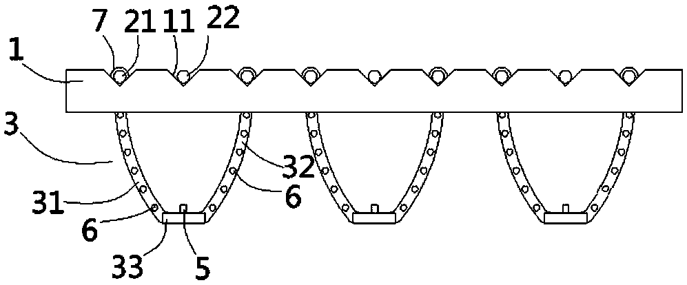
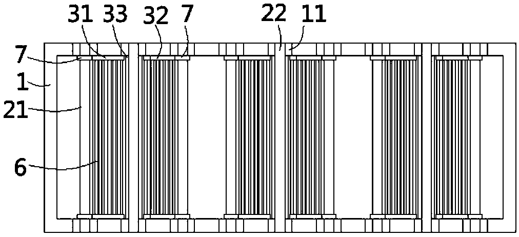
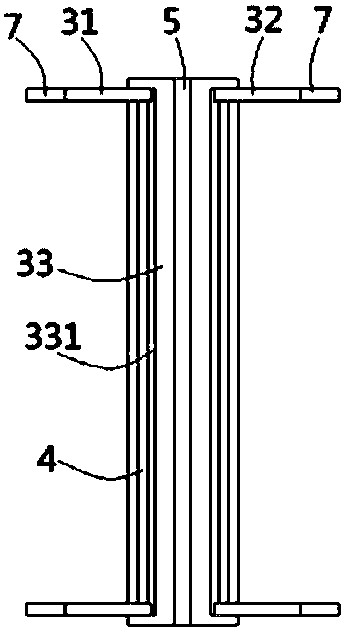
[0020] see Figure 1 to Figure 4 , the automobile radiator placement frame in a salt spray test chamber according to the present invention comprises a rectangular frame 1, and corresponding V-shaped notches 11 are formed on the two opposite sides of the upper end surface of the frame 1, the first The two ends of a support rod 21 and the second support rod 22 are erected in the V-shaped notch 11, and the adjacent first support rod 21 is provided with a support frame 3, and the support frame 3 includes a The arc-shaped first struts 31 and the second struts 32 at both ends of the adjacent first support rods 21, the horizontal third struts 33 connected to the lower ends of th...


PUM


Abstract

The invention discloses an automobile radiator placing rack in a salt spray test chamber. The automobile radiator placing rack comprises a rectangular framework, wherein corresponding V-shaped notchesare formed in two opposite side edges of the upper end surface of the framework; both ends of first supporting rods and those of second supporting rods are erected in the V-shaped notches; supportingframes are arranged on the adjacent first supporting rods, and comprises first struts, second struts and third struts; the first struts and the second struts are circular arc-shaped and correspondingly arranged at both ends of the adjacent first supporting rods; the third struts are horizontal as well as connected to the lower ends of the first supporting rods and those of the second supporting rods; the lower ends of the first struts and those of the second struts are correspondingly hinged to both sides of the third struts; baffle strips are formed at the middles of the upper end surfaces of the third struts; a plurality of transverse bearing rods are fixed between the first struts and the second struts which are arranged at both ends of the first supporting rods; and sleeves are formedat the upper ends of both the first struts and the second struts, and correspondingly inserted into both ends of the first supporting rods in a sleeving manner. By adoption of the automobile radiatorplacing rack disclosed by the invention, the placing quantity of automobile radiators can be increased.

Description

Technical field: [0001] The invention relates to the technical field of detection equipment for automobile radiators, in particular to a shelf for placing automobile radiators in a salt spray test chamber. Background technique: [0002] At present, aluminum-plastic or all-aluminum car radiators need to undergo external corrosion tests to check whether they meet the requirements for external corrosion resistance. The external corrosion test of automobile radiators generally uses 42g / L sodium chloride solution with a pH value of 2.8 to 3.0 as the corrosion solvent, and conducts a long-term test in a salt spray test chamber. However, the rack for storing automobile radiators in the existing salt spray test chamber generally has only one frame, and horizontal cross bars are arranged on the frame, so that automobile radiators can only be placed horizontally on the cross bars, and because the salt spray Above the car radiator, the sinking of the salt spray needs to be in direct c...

Claims


Application Information

Patent Timeline
IPC IPC(8): F16M11/04G01N17/00
CPCF16M11/04G01N17/00
Inventor 孙伟
Owner 淮安市中亚试验设备有限公司
Learn More