A walker device

一种器具、助行器的技术,应用在帮助人走动的器具、物理治疗、手推车等方向,能够解决制动索使用者障碍等问题

Inactive Publication Date: 2009-07-08
CARRERA OPTYL MARKETING
View PDF5 Cites 0 Cited by
  • Summary
  • Abstract
  • Description
  • Claims
  • Application Information

AI Technical Summary

Problems solved by technology

[0004] One consequence of the height-adjustable feature in this type of walker is that the length of the brake cable often presents a hindrance to the user

Method used


Image

  • A walker device
  • A walker device
  • A walker device

Examples


Embodiment Construction

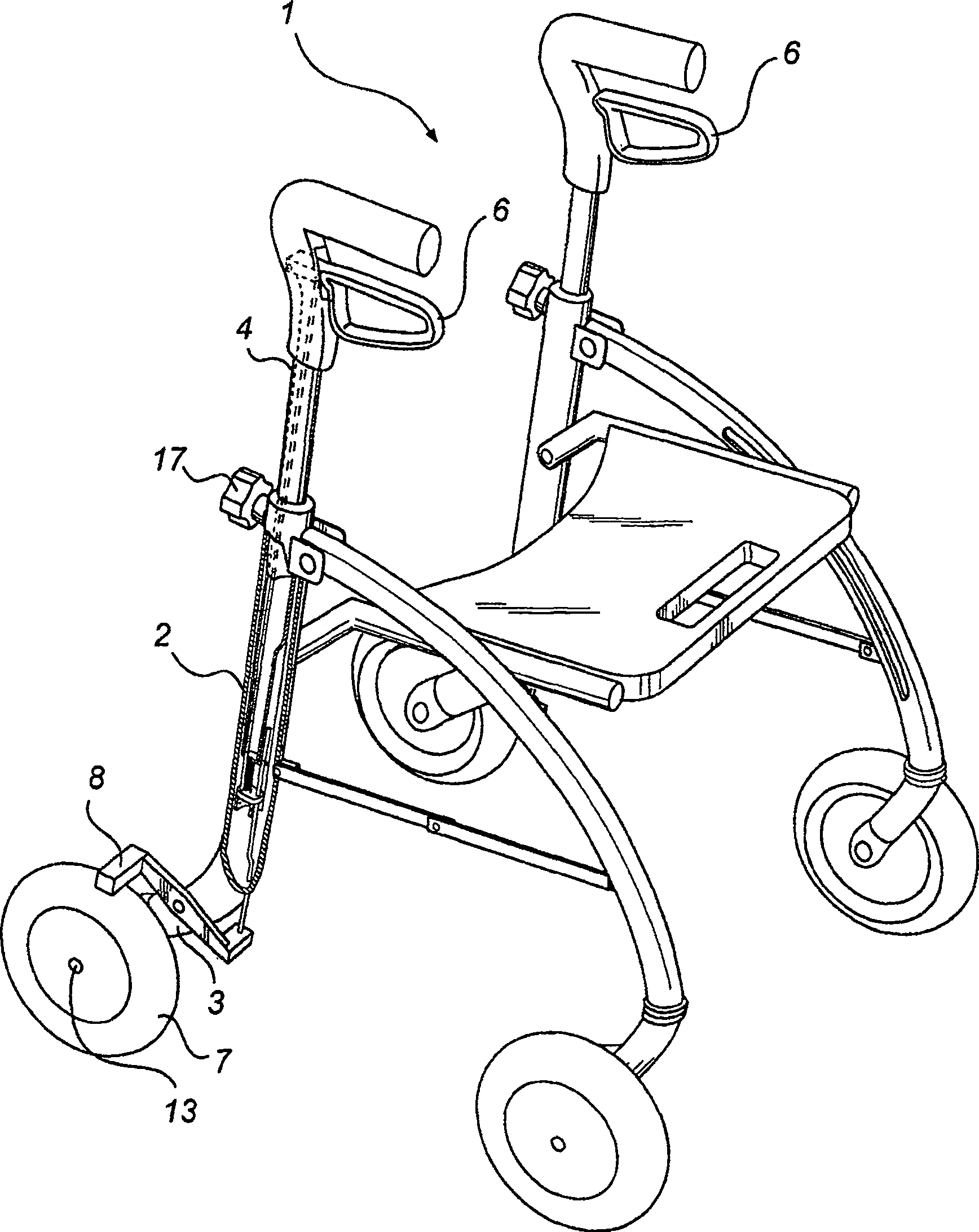
[0027] figure 1 A walker 1 according to one embodiment of the invention is shown, comprising a frame 2 . The lower end 3 of the frame supports wheels 7 which are rotatably mounted on axles 13 in the frame. The lower end 3 of the frame member 2 also supports a brake 8 mounted adjacent to the wheel 7 at a predetermined radial distance from the latter.

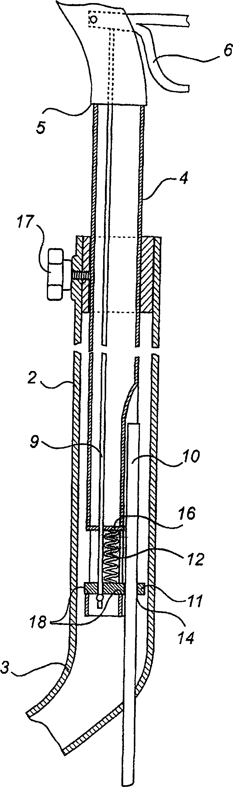
[0028] An adjustable handle support rod 4 is provided at the upper end of the frame member 2 . The frame member 2 is preferably adapted to receive a handle support rod 4 so that the latter can be fitted in a part of the frame member 2 . Corresponding interconnecting portions of these components suitably have substantially similar complementary cross-sectional shapes, such as circular, oval or polygonal shapes. according to figure 1 In the embodiment shown, the lower end of the handle support rod 4 is slightly narrower than the rest of the support rod extending therefrom. This narrow portion of the handle support rod 4 can, f...


PUM


Abstract

A brake control (6) provided at the top end (5) of a handle shaft (4) is freely movable between braking and released positions. The distance between the brake control and the wheel (7) at the bottom end (3) of the rollator frame (2) is adjustable. An upper transmission device (9) is connected to the brake control, a lower transmission device (10) is connected to the brake part (8) acting against the wheel and a coupling device (11) connects the two transmission devices together, the latter being freely movable relative to each other when the brake control is in the released position. When the brake control is in the locking position, the transmission devices are hitched together, causing a braking force to be transmitted to the brake part.

Description

technical field [0001] The present invention relates to a walker device or rollator comprising: at least one frame member having a lower end; at least one handle support rod having an upper end; arranged substantially at the upper end of the handle support rod a brake control device movable between a neutral position (neutral position) and a brake-application position (brake-application position); substantially at the wheel at the lower end of the frame member, said wheel and the distance between the brake control devices is variable; the brake adjacent the wheel; the upper force transmission member connected to the brake control device; the lower force transmission member connected to the brake member; Connecting means for connecting the upper and lower force transmission members together. Background technique [0002] Walking aids or walking aids of the above-mentioned type are well known. Walkers of this type are wheeled appliances on which motor-handicapped individuals...

Claims


Application Information

Patent Timeline
Patent Type & Authority Patents(China)
IPC IPC(8): A61H3/04B62B5/04B65G17/38B60T11/04B65G17/08B65G17/40
CPCA61H2003/046A61H3/04B62B5/04B62B2206/06B60T11/04B62B5/0447B62B5/0485
Inventor T·隆克维斯特
Owner CARRERA OPTYL MARKETING
Why Eureka
Try Eureka