
Camera support pressurization system

A pressurized system and camera technology, applied in the direction of the machine/support, camera, camera body, etc., can solve problems such as troublesome overall structure and insufficiency

Pending Publication Date: 2018-08-03
章伟松
View PDF0 Cites 0 Cited by
  • Summary
  • Abstract
  • Description
  • Claims
  • Application Information

AI Technical Summary

Problems solved by technology

[0004] The purpose of the present invention is to provide a camera support pressurization system in order to solve various troubles and overall structural deficiencies caused by the adjustment of the existing camera support.

Method used


Image

  • Camera support pressurization system
  • Camera support pressurization system
  • Camera support pressurization system

Examples


Embodiment Construction

[0017] The present invention will be described in further detail below in conjunction with the accompanying drawings.

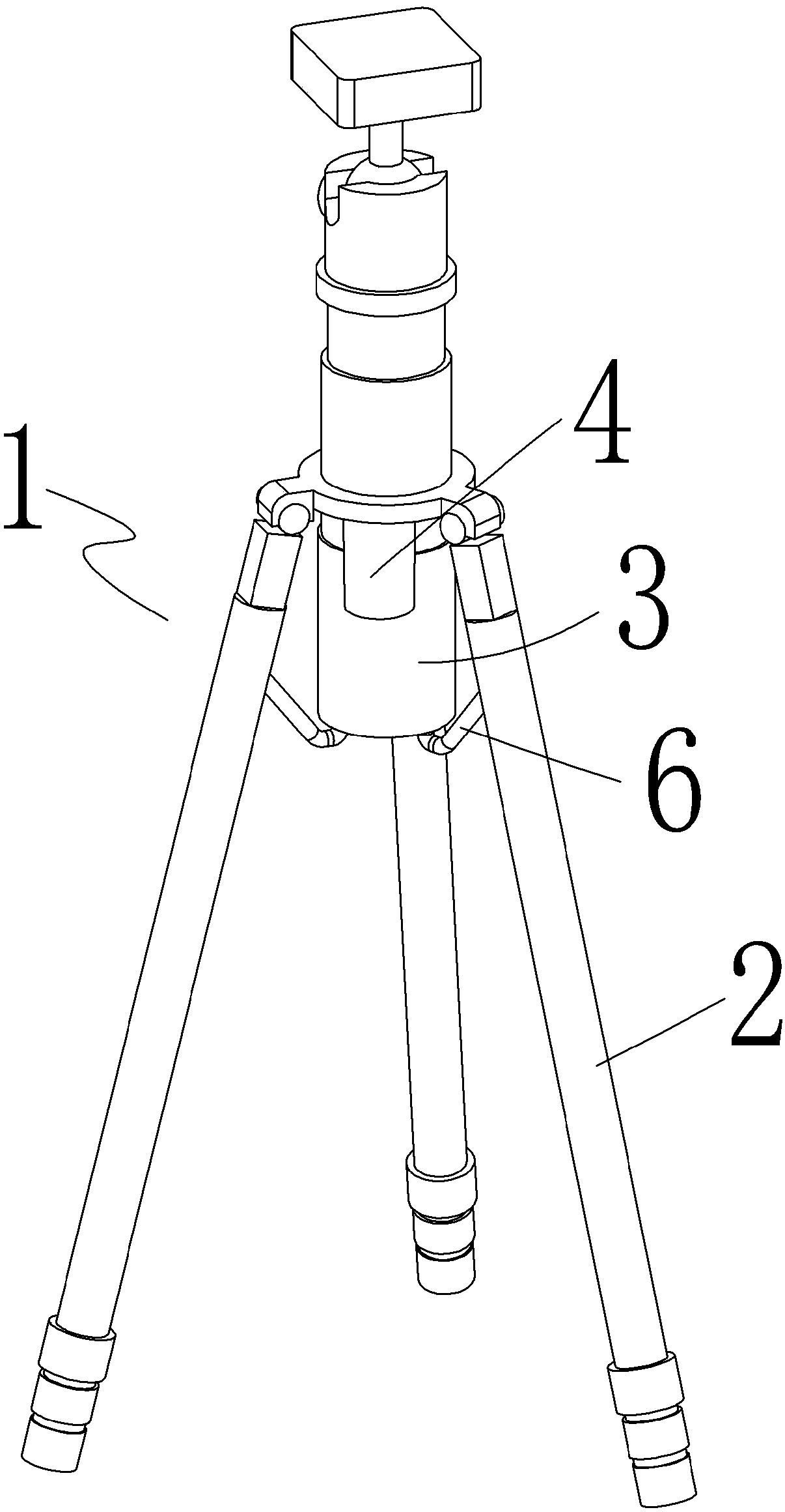
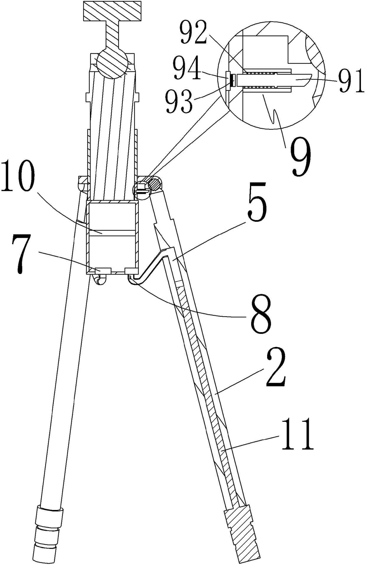
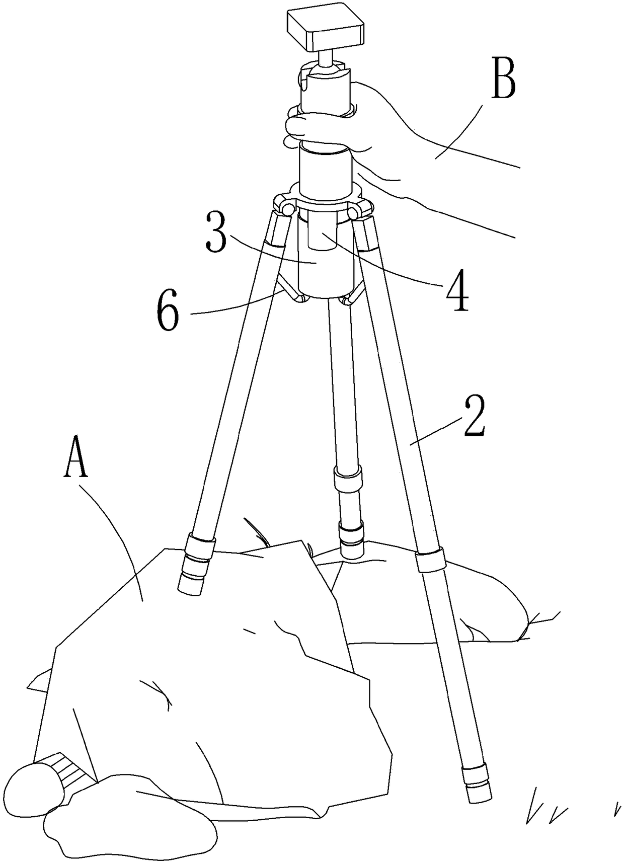
[0018] refer to figure 1 , figure 2 , camera bracket pressurization system, including frame body 1, frame body 1 has some retractable legs 2, a pressurized chamber 3 is provided under the support 1, and an air pump 4 is provided on one side of the pressurized chamber 3, and the air pressure The pump 4 is connected to the top of the pressurized chamber 3;

[0019] The pressurized chamber 3 includes several connecting pipes 6 located at the bottom and connected to the inner lumen 5 of the leg. The mouth of the connecting pipe 6 is provided with a magnetic control valve 7, and a pressure sensor 8 is also provided on one side of the magnetic control valve 7;

[0020] The main switch 9 of the pneumatic pump 4, the magnetic control valve 7 and the pressure sensor 8 is located at the hinge of the legs, which is opened when the legs are extended to the periphery, ...


PUM


Abstract

The invention discloses a camera support pressurization system. The camera support pressurization system comprises a support body, wherein a plurality of telescopic supporting legs are arranged on thesupport body; the camera support pressurization system is characterized in that a pressurization cavity is arranged at the lower part of the support, one side of the pressurization cavity is providedwith a pneumatic pump, and the pneumatic pump is connected to the upper part of the pressurization cavity; the pressurization cavity comprises a plurality of connecting pipes which are arranged at the bottom and are connected to an inner pipe cavity of the supporting legs, a magnetic control valve is arranged on the openings of the connecting pipes, and one side of the magnetic control valve is further provided with a pressure sensor; and a main switch of the pneumatic pump, the magnetic control valve and the pressure sensor is arranged at the hinged position of the supporting legs, the mainswitch is turned on when the supporting legs are unfolded towards the periphery, and the main switch is turned off when the supporting legs are folded towards the center. According to the camera support pressurization system, the supporting legs are pressurized and stretched through the pneumatic pump, when the supporting legs meet resistance in the stretching process, the pressure sensor measuresthe pressure change, the magnetic control valve is directly or indirectly controlled to cut off the air pressure from the pressurization cavity, so that the supporting legs can be stretched and keptin an stretched state; and the supporting legs do not need to be touched manually, and are automatically adjusted according to the contact surface, so that time and labor are saved, and use is convenient and fast.

Description

technical field [0001] The present invention relates to a camera mount pressurization system. Background technique [0002] The camera bracket is an important tool for stabilizing the camera. It is usually foldable or retractable. There are generally three outriggers, which are spread out and placed on the ground or objects. The camera is placed on the bracket to keep the camera stable when shooting stable. [0003] However, when the existing support is placed on the ground or an object, it is necessary to manually adjust the length and inclination of each leg to meet the stable needs of the camera when framing the view. This is troublesome, because the length change of one of the legs will cause For the change of another leg, to adjust a leg, the button must be turned off first to lock the leg, and then the other legs are adjusted, but the button always needs to be opened and closed, which is very troublesome. Contents of the invention [0004] The object of the present...

Claims


Application Information

Patent Timeline
IPC IPC(8): F16M11/32G03B17/56
CPCG03B17/561F16M11/32
Inventor 章伟松
Owner 章伟松
Learn More