Supercharge Your Innovation With Domain-Expert AI Agents!

Band-shaped occlusion means

An occlusive, arched technology, applied in the field of implants, can solve the problem of bulky small-bore catheters

Inactive Publication Date: 2018-08-03
菲姆托斯股份有限公司
View PDF6 Cites 0 Cited by
  • Summary
  • Abstract
  • Description
  • Claims
  • Application Information

AI Technical Summary

Problems solved by technology

Additionally, the implant is too bulky for small-bore catheters

Method used


Image

  • Band-shaped occlusion means
  • Band-shaped occlusion means
  • Band-shaped occlusion means

Examples


Embodiment Construction

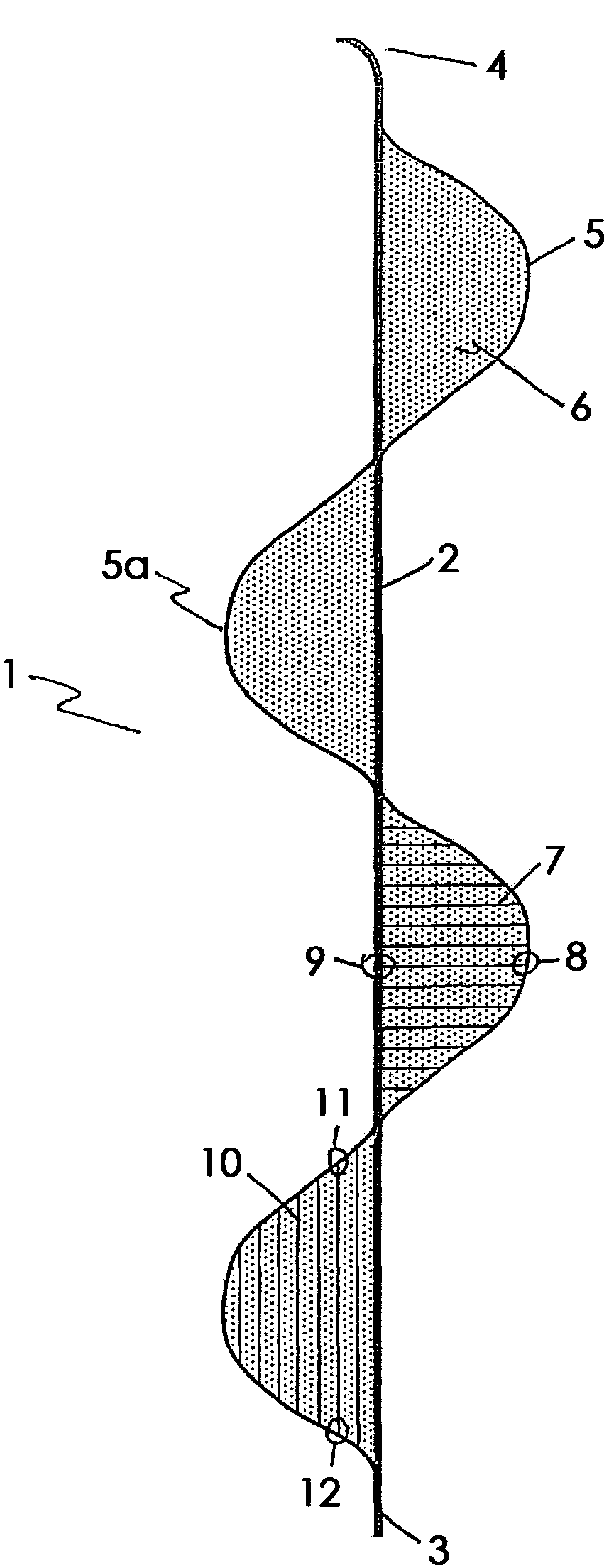
[0055] figure 1 A first embodiment 1 of the occlusive unit of the implant proposed by the invention is shown in a partially expanded, stretched, two-dimensional view outside the catheter, without assuming the final three-dimensional shape. A centrally extending axial spine 2 has a proximal end 3 and a distal end 4, arched struts 5 form wings 5a with a membrane 6 and nylon filaments 7, 10, wherein, in the arrangement 7, the nylon filaments 7, 10 are perpendicular to the spine 2, which is fastened to the arched struts 5, 8 and the spine 2, 9, or in the case of arrangement 10, nylon wires 7, 10 extending parallel to the axial struts 2, the ends 11, 12 being fixed to the arched struts 5.

[0056] figure 2 is a schematic illustration of a first variant of a second embodiment 13 of an implant outside a placement catheter according to the present invention, in a partially unfolded, stretched two-dimensional view, without assuming the final three-dimensional shape (see image 3 , ...


PUM


Abstract

The invention relates to an implant for vascular use, which implant can be transported through a catheter and is intended in particular to influence the flow of blood in the area of arteriovenous defects, for example fistulas and aneurysms, to fill the bulge caused by the defect, to promote clot formation and to cover the neck of the defect. The implant according to the invention has an occlusionunit (1, 13) of three-dimensional shape composed of a plurality of sub-units (5a, 14) made from a framework of struts (5, 16, 17), wherein a cover, preferably a membrane (6), is located between struts(5, 16, 17).

Description

technical field [0001] The present invention relates to an implant for vascular applications that can be implanted through a catheter and is particularly intended to affect blood flow in areas of arteriovenous malformations, such as fistulas and aneurysms, to fill said Cystic dilatation of malformation, and promotion of thrombus formation. Background technique [0002] Aneurysms are usually sac-like dilations of the vessel wall and occur mainly in areas of structural weakness of the vessel wall due to the constant pressure of the blood. As a result, the inner walls of the aneurysm are very sensitive and susceptible to damage that could lead to rupture of the aneurysm sac. As a result, considerable health damage may occur, such as neurological disorders, which may even lead to the patient's death. Primarily this may be the case when this deformity occurs in an area of ​​the brain. [0003] Current endovascular methods for treating aneurysms are well known and two methods i...

Claims


Application Information

Patent Timeline
Patent Type & Authority Applications(China)
IPC IPC(8): A61B17/12
CPCA61B17/12113A61B17/1215A61B17/12163A61B17/12172A61B17/12177A61B2017/12054A61B17/12145A61B2017/00867A61B2017/00893A61L31/04A61L31/16A61B2017/12063A61B2017/12068A61B17/12031
Inventor H·蒙斯塔特H·亨克斯R·汉内斯
Owner 菲姆托斯股份有限公司
Features
  • R&D
  • Intellectual Property
  • Life Sciences
  • Materials
  • Tech Scout
  • Unparalleled Data Quality
  • Higher Quality Content
  • 60% Fewer Hallucinations
Learn More