Device allowing an alimentary bolus flow between two stomas

An equipment and stoma technology, which is applied in the field of equipment that can realize bolus flow between two stoma, and can solve the problems of unsatisfactory sealing of check valve and the like

Active Publication Date: 2018-08-03
CENT HOSPITALER & UNIV DE LILLE
View PDF7 Cites 1 Cited by
  • Summary
  • Abstract
  • Description
  • Claims
  • Application Information

AI Technical Summary

Problems solved by technology

[0004] Moreover, the sealing of the above two check valves is not satisfactory

Method used


Image

  • Device allowing an alimentary bolus flow between two stomas
  • Device allowing an alimentary bolus flow between two stomas
  • Device allowing an alimentary bolus flow between two stomas

Examples


Embodiment Construction

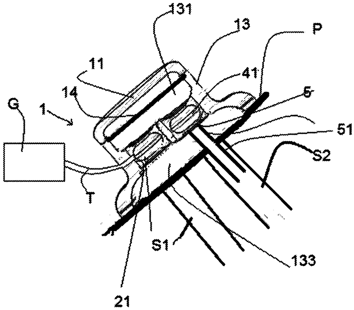
[0038] refer to figure 1 , the device comprises a single manifold 1 constituting first and second sealed connection means to upstream and downstream stomas S1 and S2 performed on the patient's abdomen. The device is suitable for closed ostomies that can be covered by a single manifold. The manifold 1 comprises a cover 11 secured to a manifold body 13 . The manifold body 13 has a membrane housing 131 containing the membrane 14 . The suction conduit 3 and the discharge conduit 5 are arranged in the manifold body 13 and lead to the membrane housing 131 . The manifold body 13 also comprises a collection housing 133 in which the suction duct 3 and the discharge duct 5 also open. The membrane housing 131 and the collecting housing 133 are connected to each other by the suction conduit 3 and the discharge conduit 5 . The collection housing 133 is fixed on the skin P of the patient's abdomen, above the two stomas S1 and S2. The discharge conduit 5 comprises a nozzle which passes ...


PUM


Abstract

The present invention concerns a device allowing the creation of an alimentary bolus flow between two stomas (S1; S2), comprising: means forming a pump (14, 131); - first / second sealed connection means (1) capable of connecting the suction opening to an upstream / downstream stoma (S1; S2) located on the abdominal wall of a patient; and first and / or second anti-reflux means (21, 3; 41, 3). Accordingto the invention, the first and / or second anti-reflux means comprise a cavity (21; 41) into which the alimentary bolus passes, an inflatable balloon (3) mounted in the cavity and means (G) for inflating the balloon, that make it possible to modify the inflation of the latter, and the balloon (3) is shaped to shift from an open position in which the balloon (3) is partially inflated and has a neck(32) allowing the passage of the alimentary bolus, to a closed position in which the balloon (3) is more inflated than in the open position and in which the balloon is in contact with the wall of thecavity and the neck (32) is sealed as a result of the portion of the wall of the balloon defining the neck (32) being compressed against itself, at least over a portion of the height of the neck (32).

Description

technical field [0001] The present application relates to a device enabling bolus flow between two stomas, a device of this type comprising anti-reflux means comprising a balloon having a neck for the passage of a bolus . Background technique [0002] Document WO 2014 / 122378 describes a device for circulating a bolus flow between two stomas. The device includes suction and discharge catheters. The bolus drains naturally from the first stoma to the manifold of the above-mentioned device. The suction conduit allows suction of the bolus contained in the manifold to the suction conduit of the device. This allows in turn to expel the inhaled food bolus to the second intestinal portion at the second stoma level. In the above-mentioned documents, the suction conduit and the discharge conduit are each equipped with a check valve. Such a check valve may be of the duckbill type, ie a duckbill formed by two flexible lips which can be moved away from each other in order to pass the...

Claims


Application Information

Patent Timeline
Patent Type & Authority Applications(China)
IPC IPC(8): A61F5/44A61M1/00A61F5/445
CPCA61F5/44A61F5/445A61F5/4405A61M1/80A61M2210/1042
Inventor R.洛吉尔J-P.索赞斯基J-R.扎穆什埃勒潘马布拉
Owner CENT HOSPITALER & UNIV DE LILLE
Why Eureka
Try Eureka