
A ct power-taking device that selects the working mode according to the cable load and battery status

A technology of working mode and power-taking device, which is applied in the direction of adjusting electric variables, control/regulation systems, instruments, etc., and can solve problems such as interference with the normal operation of monitoring devices, monitoring instruments that cannot continue to work, and lack of intelligent control functions.

Active Publication Date: 2017-08-08
SHANGHAI MUNICIPAL ELECTRIC POWER CO +1
View PDF5 Cites 0 Cited by
  • Summary
  • Abstract
  • Description
  • Claims
  • Application Information

AI Technical Summary

Problems solved by technology

The cable monitoring device usually adopts the 220V mains power supply provided by the substation or the urban power supply system, and if there is often no working power supply for the monitoring system at the middle joint of the cable line or in some remote areas, or in the case of a sudden power failure of the mains, the monitoring The instrument will no longer work
At present, there are many kinds of power supply devices on the market, such as: solar power generation, wind power generation, etc., but due to unstable power supply, bulky equipment, and difficult installation, they have not been popularized for the time being.
Similar power-taking CT devices have been partially used in the market, and the device system is as follows: figure 1 As shown, the load AC power on the cable line is obtained through the power-taking CT, and the obtained load AC power is converted into the DC power required by various power consumption devices through the rectifier, and finally the DC current is provided to the online monitoring device to ensure the normal operation of the power consumption devices. Due to the lack of intelligent control function of the existing power-taking CT device, when the cable line current is in a small current state close to no-load, the power-taking CT device fails to provide effective power for various monitoring devices, which often leads to battery depletion , so that the device is in a dormant state for a long time and cannot obtain valid data; and when the cable line current is in a state of large current exceeding the rated current, the excessive current may have impact damage to the power supply device, and may even interfere with the normal monitoring device. operate

Method used

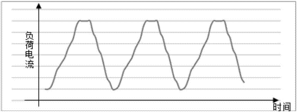

Image

  • A ct power-taking device that selects the working mode according to the cable load and battery status
  • A ct power-taking device that selects the working mode according to the cable load and battery status
  • A ct power-taking device that selects the working mode according to the cable load and battery status

Examples


Embodiment

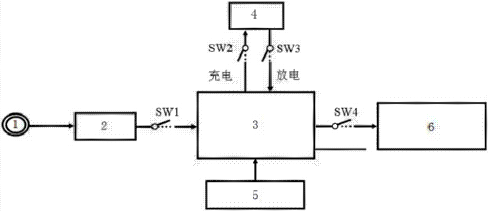
[0035] Such as figure 2 As shown, the purpose of the present invention is to provide a CT power-taking device that selects the working mode according to the cable load and the battery state, adding the intelligent control module 3, and mainly through the joint evaluation of the cable load current management mechanism and the battery power management mechanism to adjust the on-line Monitor the power consumption rhythm of the device 6 to ensure that the device works as normal as possible under different load currents. It includes a power-taking CT1, a rectifier 2, an intelligent control module 3, a battery 4 and a temperature sensor 5, which are installed on the cable line The power-taking CT1 is connected to the rectifier 2 through the power line, the rectifier 2 is connected to the intelligent control module 3 through the power line, the battery 4 is connected to the intelligent control module 3 through the power line, and the temperature sensor 5 is connected to the intellige...


PUM


Abstract

The invention relates to a CT power pick device capable of selecting the work mode according to cable load and battery status. The work mode of the CT power pick device is selected according to the cable load, current status and battery electric quantity, and the power utilization rhythm of an online monitoring device is adjusted. The CT power pick device comprises a power pick CT, a rectifier, an intelligent control module, a battery and a temperature sensor, wherein the power pick CT, the rectifier and the intelligent control module are sequentially connected through a power line, and the intelligent control module is connected with the battery and the online monitoring device through power lines and is connected with the temperature sensor through a power line and a signal line. Compared with the prior art, the CT power pick device has the advantages of unlimited installation, multiple work modes, comprehensive consideration and the like.

Description

technical field [0001] The invention relates to the technical field of intelligent power supplies, in particular to a CT power-taking device that selects an operating mode according to cable load and battery status. Background technique [0002] At present, for the stable operation of the power system, various monitoring devices (such as PDM) need to be installed on the cable equipment. The cable monitoring device usually adopts the 220V mains power supply provided by the substation or the urban power supply system, and if there is often no working power supply for the monitoring system at the middle joint of the cable line or in some remote areas, or in the case of a sudden power failure of the mains, the monitoring The instrument will no longer work. At present, there are many kinds of power supply devices on the market, such as: solar power generation, wind power generation, etc., but due to the unstable power supply, bulky equipment, and difficult installation, they hav...

Claims


Application Information

Patent Timeline
Patent Type & Authority Patents(China)
IPC IPC(8): G05F1/625
CPCG05F1/625
Inventor 高小庆王媚周咏晨陈越超何邦乐原佳亮李红亮沈寅喆宣辰杨王骁迪崔亮邹翔宇东盛刚崔健潘达任李志勇
Owner SHANGHAI MUNICIPAL ELECTRIC POWER CO
Learn More