Parallel piezoelectric micromotion platform

A micro-movement platform, piezoelectric technology, applied in the direction of piezoelectric device/electrostrictive device, piezoelectric device or electrostrictive device parts, device parts, etc., can solve the problem of heavy mass, low natural frequency, Displacement sensor installation limitations and other issues, to achieve the effect of small mass, high natural frequency, and large overall stiffness

Inactive Publication Date: 2013-06-19
NINGBO UNIV
View PDF5 Cites 0 Cited by
  • Summary
  • Abstract
  • Description
  • Claims
  • Application Information

AI Technical Summary

Problems solved by technology

[0004] (1) Only one-dimensional or two-dimensional translational micro-displacement can be produced, and no rotational micro-displacement can be produced. If translational and rotational micro-displacement is to be produced at the same time, it needs to be superimposed on the moving platform that realizes translational micro-displacement. A moving platform that realizes rotating micro-displacement in one dimension, which makes the entire micro-moving platform complex in structure, large in size, heavy in mass, and low in natural frequency;
[0005] (2) The installation of displacement sensors is limited, especially for precision displacement sensors such as capacitive sensors and differential transformer inductive sensors, only the non-driving side of the moving platform can be used as the measured surface, and displacement sensors and piezoelectric sensors are also required. The axis of the ceramic actuator should be in the vertical bisector of the side of the moving platform

Method used


Image

  • Parallel piezoelectric micromotion platform
  • Parallel piezoelectric micromotion platform
  • Parallel piezoelectric micromotion platform

Examples


Embodiment 1

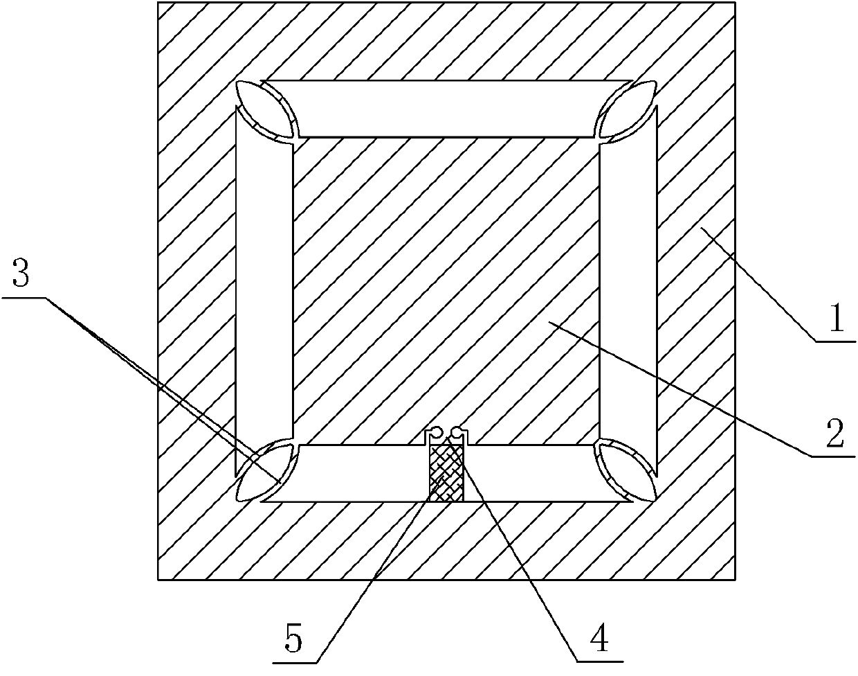
[0025] Embodiment one: if image 3 As shown, a parallel piezoelectric micro-moving platform includes a platform body 1 and a moving platform 2, the moving platform 2 is arranged in the platform body 1, and the four right angles between the platform body 1 and the moving platform 2 are integrally provided with elastic deformation Body 3, the elastic deformation body 3 is composed of two arc-shaped elastic thin plates with the same radius and arc length, which are convex and concave, and the two ends of the arc-shaped elastic thin plates are respectively at right angles to the inner part of the platform body 1, The outer right angle of the moving platform 2 is integrally connected, and one side of the moving platform 2 is provided with a guide hinge 4, the guide hinge 4 is arranged at the exact center of the side, and the inner surface of the table body 1 facing the guide hinge 4 A piezoelectric ceramic actuator 5 is fixedly arranged therebetween, and the cross section of the gu...

Embodiment 2

[0027] Embodiment two: if Figure 4 As shown, the other structures are the same as those in Embodiment 1, except that two guide hinges 4 at the same height are arranged on one side of the moving platform 2, and the two guide hinges 4 are symmetrical about the vertical bisector A-A of the side.

[0028] In this embodiment, when the piezoelectric ceramic actuator 5 on the left is elongated and deformed under the action of the driving voltage and the piezoelectric ceramic actuator 5 on the right is not affected by the driving voltage, the moving platform 2 passes through its top. The vertical line at the center of the surface (or bottom surface) produces a one-dimensional clockwise rotation micro-displacement; when the piezoelectric ceramic actuator 5 on the right is elongated and deformed under the action of the driving voltage, the piezoelectric ceramic actuator 5 on the left is When the driving voltage acts, the moving platform 2 generates a one-dimensional counterclockwise ro...

Embodiment 3

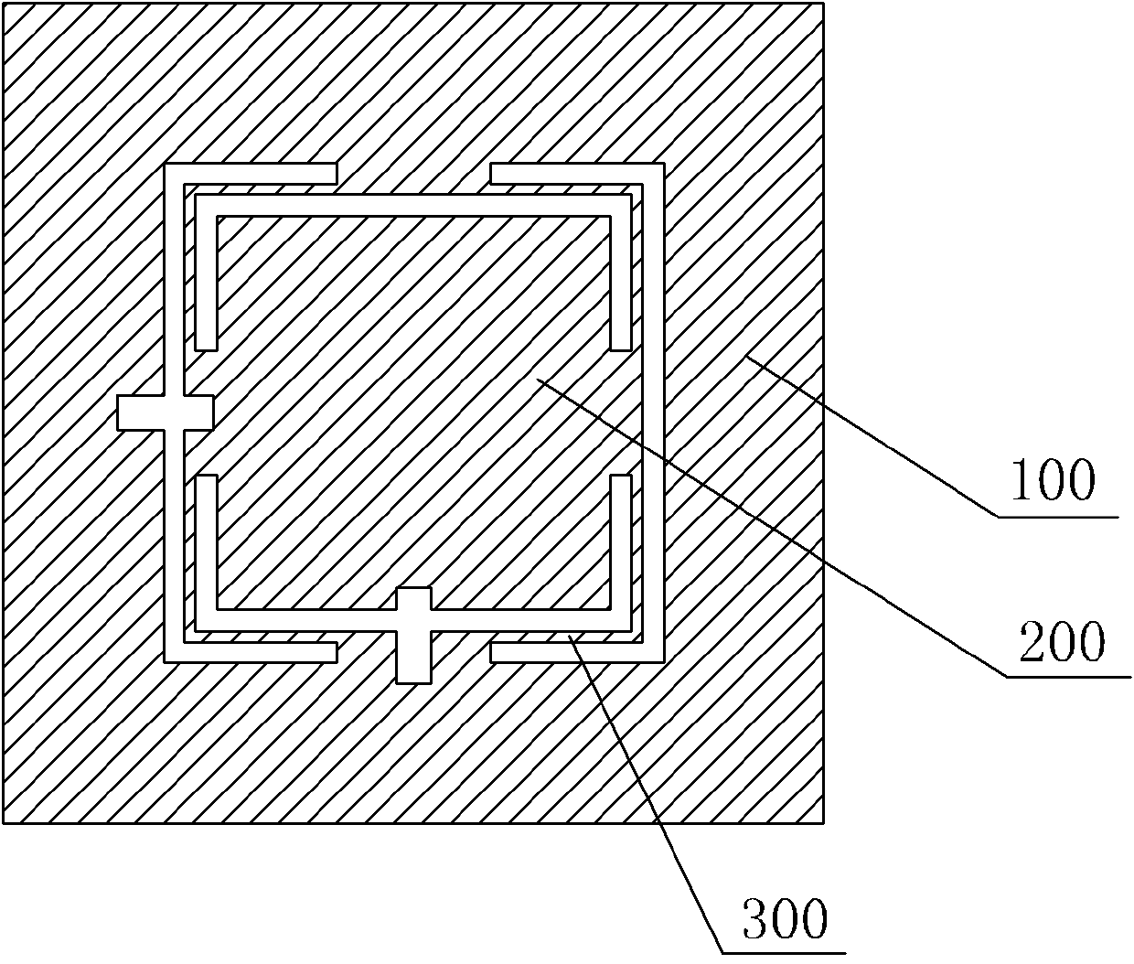
[0029] Embodiment three: as Figure 5 As shown, the other structures are the same as those in Embodiment 1, except that a guide hinge 4 is respectively provided on two mutually perpendicular sides of the moving platform 2, and the guide hinge 4 is arranged at the exact center of the side where it is located.

[0030] In this embodiment, when the two piezoelectric ceramic actuators 5 are respectively elongated and deformed under the action of the driving voltage, the moving platform 2 produces a two-dimensional translational micro-displacement along the driving direction.


PUM


Abstract

The invention discloses a parallel piezoelectric micromotion platform which comprises a platform body and a moving platform. The parallel piezoelectric micromotion platform is characterized in that elastic deformation bodies are integrally arranged at four right angles between the platform body and the moving platform; each elastic deformation body comprises two oppositely-arranged convex-concavecircular arc-shaped elastic thin sheets with equal diameters and arc lengths; both ends of each circular arc-shaped elastic thin sheet are integrally connected with the internal right angle of the platform body and the external right angle of the moving platform; at least one guide hinge is arranged on at least one side surface of the moving platform; a piezoelectric ceramic actuator is fixedly arranged between the guide hinge and the inner side surface of the platform body right opposite to the guide hinge; and the transverse cross section of the guide hinge is coincided with that of the piezoelectric ceramic actuator. The parallel piezoelectric micromotion platform has the advantages that both the translational micro-displacement and the rotary micro-displacement can be realized, so that the one-dimensional, the two-dimensional and the three-dimensional micro-displacement can be conveniently realized; the parallel piezoelectric micromotion platform has high integral rigidity and natural frequency; and the installation of the displacement sensor is not limited.

Description

technical field [0001] The invention relates to a micro-displacement mechanism used in micro / nano positioning systems such as ultra-precision machining and cell micro-operation, in particular to a parallel piezoelectric micro-motion platform. Background technique [0002] The piezoelectric micro-motion platform is a micro-displacement mechanism driven by a piezoelectric ceramic actuator that can produce micron or nanometer-level motion accuracy and motion resolution. It can be applied to ultra-precision machining, large-scale integrated circuit manufacturing, and scanning probe microscopy. , bioengineering and other cutting-edge technology fields. [0003] Parallel piezoelectric micro-motion platform is a mechanism that realizes micro-motion in each direction of motion only through a group of elastic units and a moving platform. The series piezoelectric micro-motion platform has a simple and compact structure and a large effective working surface; at the same time, since ...

Claims


Application Information

Patent Timeline
Patent Type & Authority Patents(China)
IPC IPC(8): H01L41/09H01L41/04
Inventor 崔玉国淳华李勇郑绍雍
Owner NINGBO UNIV
Why Eureka
Try Eureka