Vehicle Pneumatic Tires

A technology for pneumatic tires and vehicles, applied in vehicle parts, tire parts, tire treads/tread patterns, etc., can solve problems such as reducing lateral rigidity, achieve uniform circumferential rigidity, and improve the effect of snow-snow friction

Active Publication Date: 2020-09-01
CONTINENTAL REIFEN DEUTSCHLAND GMBH
View PDF9 Cites 0 Cited by
  • Summary
  • Abstract
  • Description
  • Claims
  • Application Information

AI Technical Summary

Problems solved by technology

The division of the shoulder blocks into two parts by additional grooves known from EP 2222 481 B1 improves drainage but reduces the lateral rigidity required for dry operation in this area

Method used


Image

  • Vehicle Pneumatic Tires

Examples


Embodiment Construction

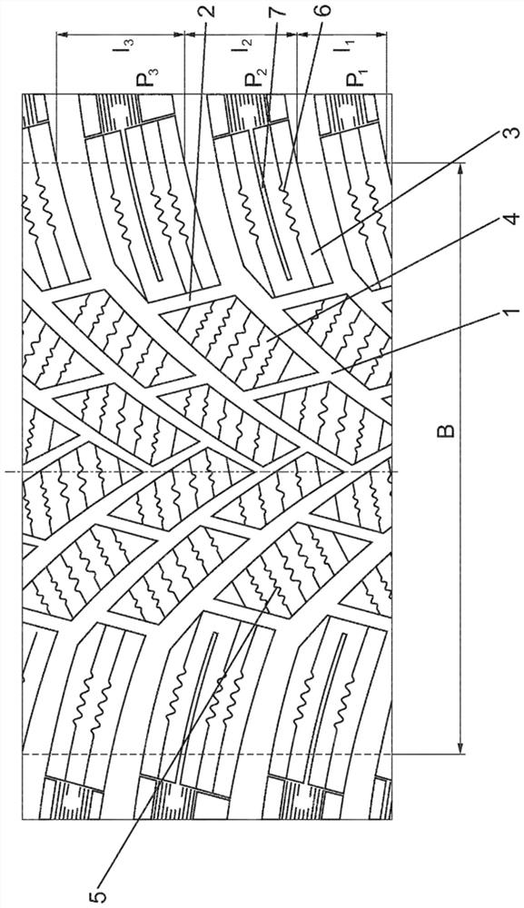
[0010] exist figure 1 The treads shown in are provided for winter tires or all-season tires for passenger cars, vans, etc. and are designed as a function of the direction of travel. Let B denote the width of the portion of the tread that is in contact with the ground, ie the width over which the tire contacts the ground when rolling. The portion of the tread that contacts the ground conforms to the ground contact area (Footprint) measured statically in accordance with the E.T.R.T.O.

[0011] In the embodiment shown, the tread is provided over its width B with diagonal grooves 1 extending V-shaped and divided into shoulders by circumferential grooves 2 extending between adjacent diagonal grooves 1 Side blocks 3 and a central block 4 arranged in the middle region of the tread. Diagonal sipe 1 is the main sipe of the tread and extends in the central region of the tread at an angle α of ≤ 60°, in particular 25° to 40°, with respect to the circumferential direction, in the direct...


PUM


Abstract

The invention relates to pneumatic vehicle tires for passenger vehicles, in particular for use under winter driving conditions, comprising a tread which is segmented by grooves (1), in particular diagonal grooves or transverse grooves, and by circumferential grooves (2) in profiled blocks (3, 4) which are provided with a respective number of incisions (5, 6, 7) and which have shoulder-side profiled blocks (3). Grooves (1) run at an angle of 60° to 85° relative to the circumferential direction in the shoulder-side profiled blocks (3), the incisions (6, 7) extend at least substantially parallel to the grooves (1), and at least two incisions (6) have a width of 0.4 mm to 0.6 mm. Each diagonal groove (1) together with the profiled blocks (3, 4) directly adjoining the diagonal groove forms a pitch (P1, P2, P3). The pitches (P1, P2, P3) are provided in at least two different pitch lengths and have correspondingly different circumferential lengths (L1, L2, L3) at the edge of the ground contact area of the tire. At least two incisions (6) with a width of 0.4 mm to 0.6 mm and an additional incision (7), which has a width of 1.1 mm to 2.7 mm, between two of said incisions (6) run in the shoulder-side profiled blocks (3) with pitches (P2, P3) with a circumferential length (L2, L3) of at least 28 mm.

Description

technical field [0001] The invention relates to a pneumatic vehicle tire for passenger cars, especially for use in winter driving conditions, which has a tread which is respectively grooved, in particular diagonally or transversely and also circumferentially The tread is divided into blocks provided with a plurality of incisions, the blocks comprising shoulder-side blocks in which the grooves are at 60° to 85° with respect to the circumferential direction corners, the incisions extend at least substantially parallel to the sipe and at least two incisions have a width of 0.4 mm to 0.6 mm, wherein each diagonal sipe forms a node jointly with the blocks directly adjoining the sipe pitches, wherein these pitches are provided in at least two different pitch lengths and have corresponding different circumferential lengths at the edge of the bottom bearing surface of the tyre. Background technique [0002] A pneumatic vehicle tire of this type is known, for example, from EP 2 222 ...

Claims


Application Information

Patent Timeline
Patent Type & Authority Patents(China)
IPC IPC(8): B60C11/03
CPCB60C11/0302B60C11/0318
Inventor 于尔根·布罗克曼弗朗茨·丁斯图贝尔马蒂亚斯·森
Owner CONTINENTAL REIFEN DEUTSCHLAND GMBH
Why Eureka
Try Eureka