

Security system with Anti-tampering sensors and cybersecurity
A technology of sensors and sensor signals, applied in anti-theft alarms, non-mechanical transmission-operated locks, instruments, etc.
- Summary
- Abstract
- Description
- Claims
- Application Information
AI Technical Summary
Problems solved by technology
Method used
Image

Examples
Embodiment Construction
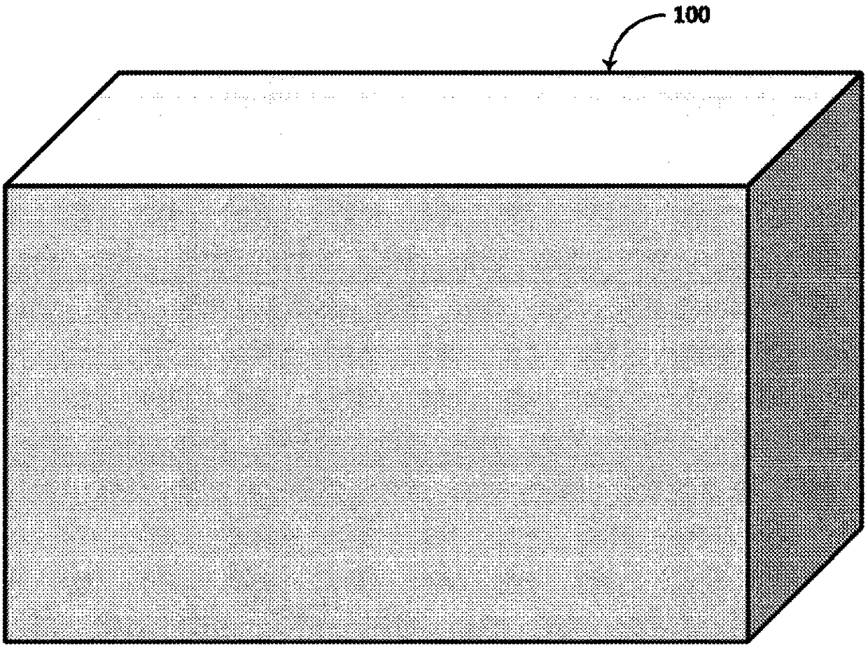
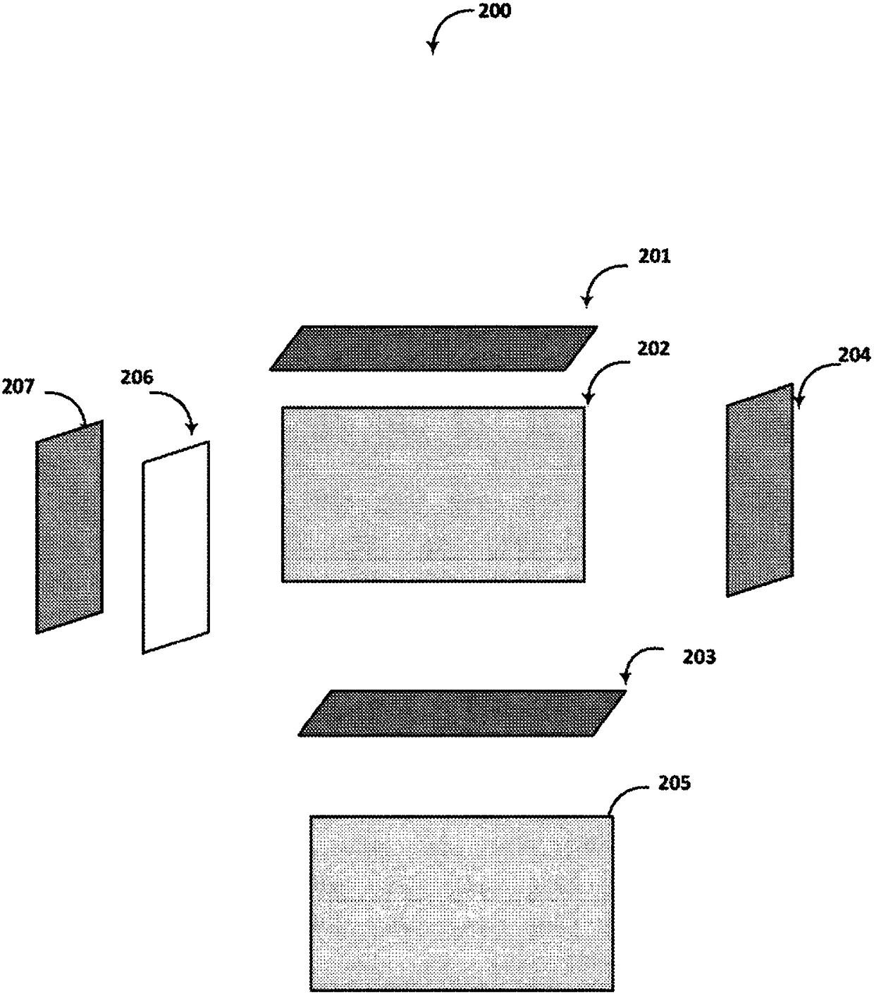
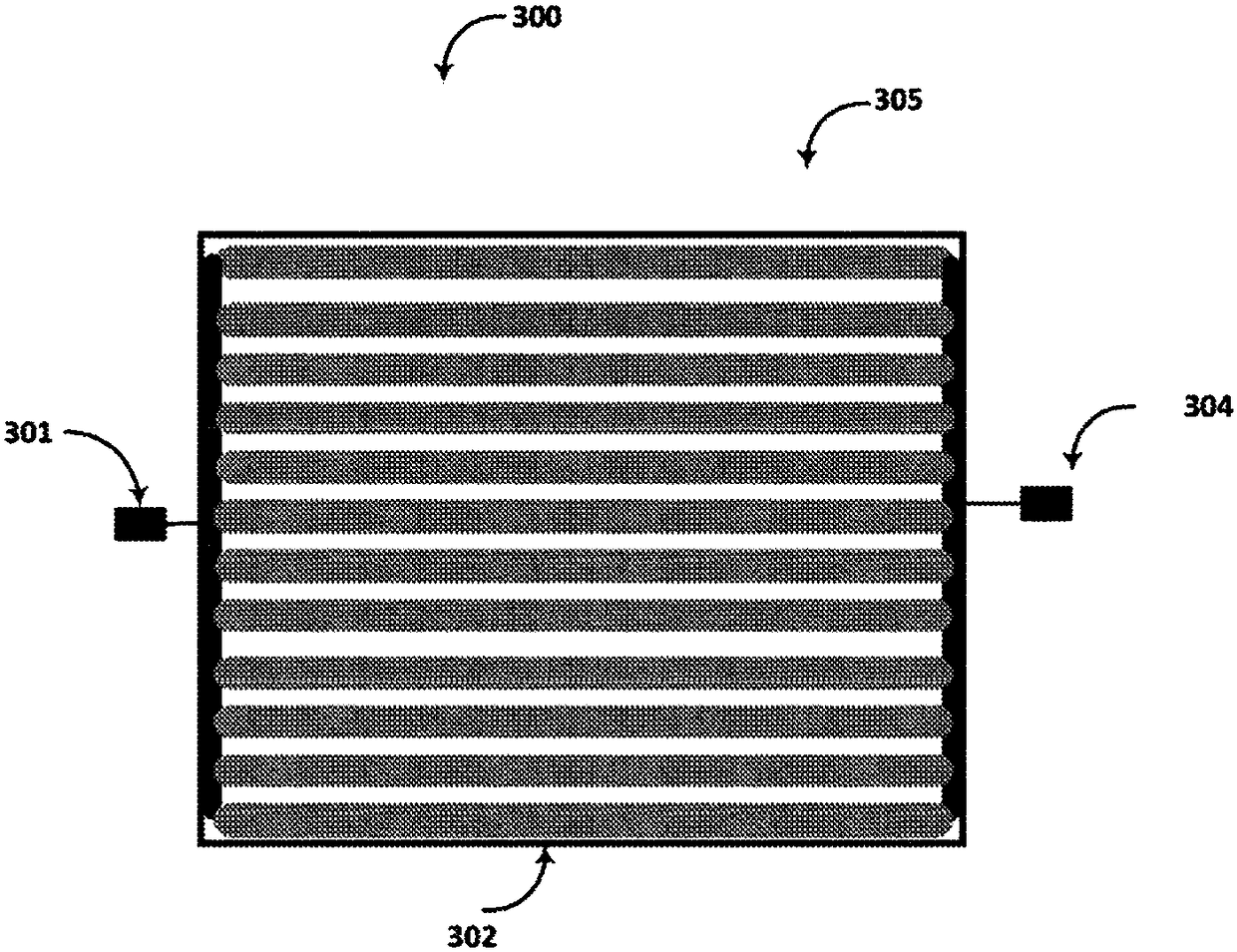
[0057] As will be elaborated in further detail below, one aspect relates to safety systems and sensor arrangements. Part of a security system may include a lock having electronic, wireless and mechanical features, sometimes referred to herein as an "eLockBox". A sensor may be a loop of electrical conductors, or a loop of optical waveguides such as fiber optic cables. Such sensors may be physically attached to the eLockBox, or placed remotely from the eLockBox and linked together via wireless connections using various bands of the electromagnetic spectrum. In some embodiments, the sensor coupled to the eLockBox may be an arrangement of electrical conductors covering six sides (sides, sides, sides) of the interior of the container, including the bottom, top, two sides, and end wall. This configuration may be referred to herein as a "shield". In other embodiments, the sensor may be an arrangement of optical waveguides, such as fiber optic cables, that covers six sides of the i...
PUM
| Property | Measurement | Unit |
|---|---|---|
| Length | aaaaa | aaaaa |
Abstract
Description
Claims
Application Information