Threshing device

A technology of threshing device and threshing section, which is applied in the direction of threshing equipment, application, agricultural machinery and implements, etc. It can solve the problem that the cleaning air cannot be increased efficiently, and achieve the effect of increasing the air volume and increasing the opening area

Inactive Publication Date: 2018-08-07
KUBOTA LTD
View PDF8 Cites 5 Cited by
  • Summary
  • Abstract
  • Description
  • Claims
  • Application Information

AI Technical Summary

Problems solved by technology

However, if the premise is not to increase the amount of external air sucked into the cleaning fan casing, the load will be applied to the blower fan, and the cleaning wind cannot be increased efficiently.

Method used


Image

  • Threshing device
  • Threshing device
  • Threshing device

Examples


Embodiment Construction

[0077] 〔Basic structure of the threshing machine

[0078] Embodiment of the threshing apparatus of this invention is demonstrated based on drawing.

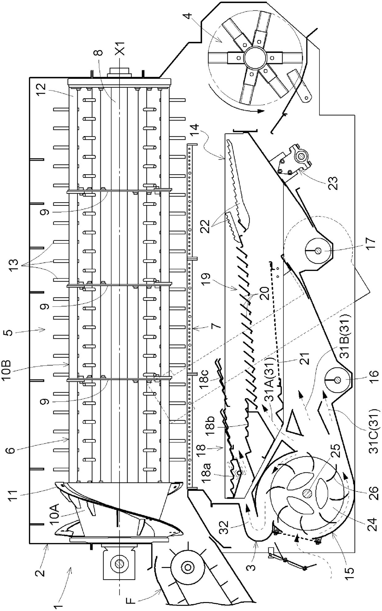
[0079] figure 1 The threshing apparatus 1 which is embodiment of this invention is shown. The threshing apparatus 1 is provided with the threshing part 2 which threshes a process object, and the sorting part 3 which sorts out the grain from the process object threshed by the threshing part 2, and collect|recovers it. The threshing part 2 is located at the upper part of the threshing device 1 , and the sorting part 3 is located at the lower part of the threshing device 1 . That is, the sorting part 3 is arrange|positioned below the threshing part 2. As shown in FIG. At the rear of the threshing device 1, a chopper 4 for chopping discharged straw and the like is installed.

[0080] A threshing chamber 5 is provided in the threshing part 2, and the threshing cylinder 6 and the screen 7 are arrange|positioned in the threshing ch...


PUM


Abstract

The invention provides a threshing device, which can efficiently increase the amount of cleaning wind from a cleaning blower fan. The threshing device comprises a threshing part, which is provided with a threshing cylinder and a screening net; and a sorting part, which is provided with a swing screening device and a cleaning blower fan. The swing screening device screens processed objects, which have been threshed by the threshing part and go through the screening net, through swinging. The cleaning blower fan is arranged in the front-lower direction of the swing screening device and deliverscleaning wind to the swing screening device. The cleaning blower fan comprises a fan for blowing cleaning wind and a cleaning blower fan shell that covers the front part and horizontal lateral part ofthe fan. The lateral part of the blower fan shell is provided with a horizontal suction opening for sucking external air, and the front part of the blower fan shell is provided with a front suction opening for sucking external air.

Description

technical field [0001] The invention relates to a threshing device. The threshing device comprises: a threshing part, which has a threshing cylinder and a screen; a sorting part, which has a swing screening device and a cleaning fan. The processed objects under the screen are screened by swinging, and the cleaning fan is arranged at the front and bottom of the swinging screening device and blows the cleaning air to the swinging screening device. Background technique [0002] For example, in the threshing device described in Patent Document 1, a lateral suction port (in the document) that sucks the outside air is formed on the side of the cleaning fan housing (in the document, "Fankees (fan housing)"). It is called "suction port (suction port)"), and by rotating the blower fan (in the document, "feather member (blade member)"), external air is sucked in from the horizontal suction port, and the cleaning wind is sent. [0003] prior art literature [0004] patent documents ...

Claims


Application Information

Patent Timeline
IPC IPC(8): A01F7/02A01F12/44
CPCA01F7/02A01F12/44A01F12/446
Inventor 北原贵志三井孝文崎山洋佑中川文里
Owner KUBOTA LTD
Why Eureka
Try Eureka