Sewage impurity separation equipment

A technology for separating equipment and impurities, applied in the direction of filtration separation, separation method, mobile filter element filter, etc., can solve the problems of difficult garbage separation, long time, etc., and achieve the effect of low manufacturing cost, simple operation and convenient use

Active Publication Date: 2018-08-07
肇庆乾正环保科技有限公司
View PDF5 Cites 3 Cited by
  • Summary
  • Abstract
  • Description
  • Claims
  • Application Information

AI Technical Summary

Problems solved by technology

[0004] In order to overcome the existing separation method using precipitation, the present invention not only takes a long time for precipitation separation, but also makes it difficult to completely separate the garbage in the sewage. The technical problem to be solved by the present invention is to provide a separation Sewage impurity separation equipment with good effect and fast separation speed

Method used


Image

  • Sewage impurity separation equipment
  • Sewage impurity separation equipment
  • Sewage impurity separation equipment

Examples


Embodiment 1

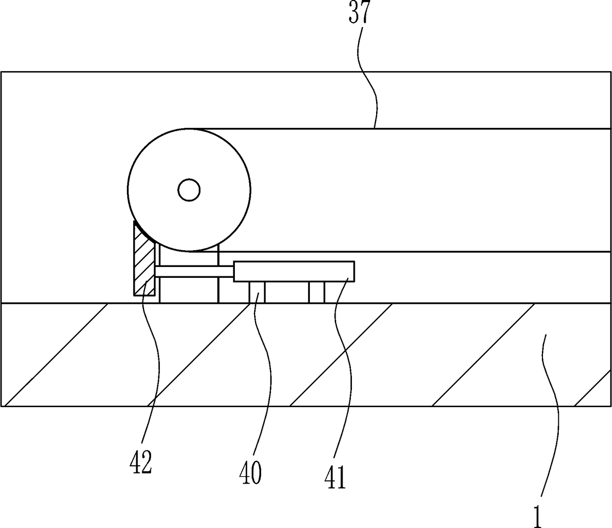
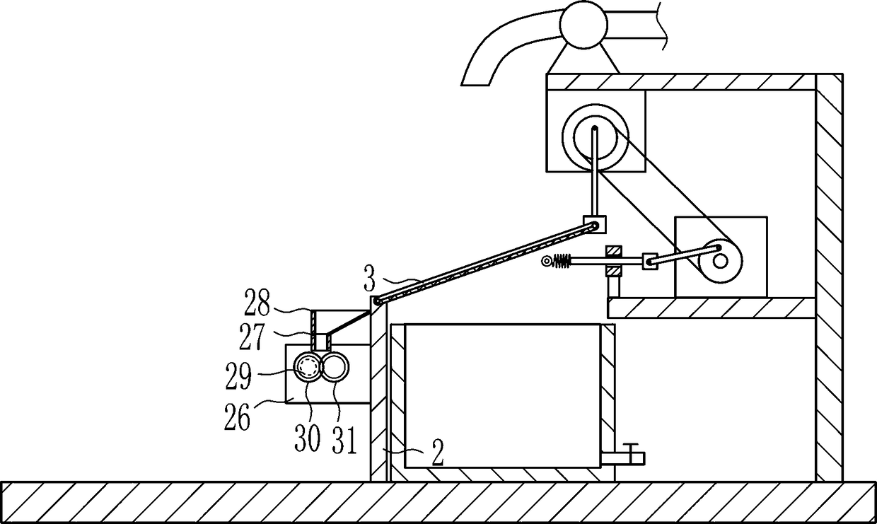
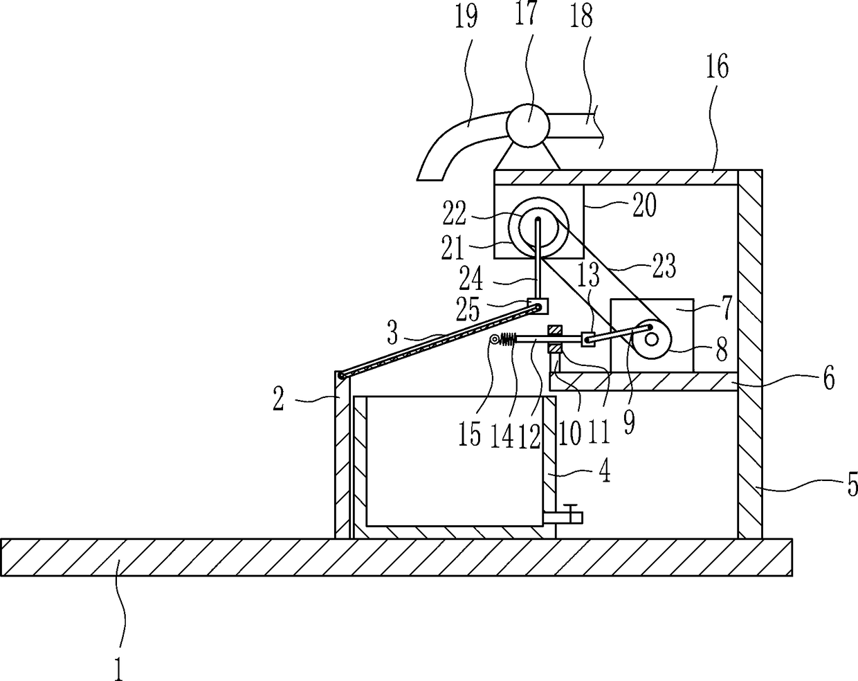
[0026] A sewage impurity separation equipment, such as Figure 1-5As shown, it includes a base 1, a first bracket 2, a filter frame 3, a collection box 4, a second bracket 5, a third bracket 6, a first fixing plate 7, a first pulley 8, a first connecting rod 9, a first A rod 10, a sliding sleeve 11, a sliding rod 12, a first fixed block 13, a first spring 14, an iron ball 15, a fourth bracket 16, a water pump 17, a water suction pipe 18, an outlet pipe 19, a second fixed plate 20, The first motor 21, the second pulley 22, the first belt 23, the second connecting rod 24 and the second fixed block 25 are fixedly connected with the first bracket 2 above the base 1, and on the upper front side of the first bracket 2 The filter frame 3 is rotatably connected, and the collection box 4 is fixedly connected above the base 1. The collection box 4 is located on the right side of the first support 2, and the second support 5 is fixedly connected on the right side above the base 1. In the...

Embodiment 2

[0028] A sewage impurity separation equipment, such as Figure 1-5 As shown, it includes a base 1, a first bracket 2, a filter frame 3, a collection box 4, a second bracket 5, a third bracket 6, a first fixing plate 7, a first pulley 8, a first connecting rod 9, a first A rod 10, a sliding sleeve 11, a sliding rod 12, a first fixed block 13, a first spring 14, an iron ball 15, a fourth bracket 16, a water pump 17, a water suction pipe 18, an outlet pipe 19, a second fixed plate 20, The first motor 21, the second pulley 22, the first belt 23, the second connecting rod 24 and the second fixed block 25 are fixedly connected with the first bracket 2 above the base 1, and on the upper front side of the first bracket 2 The filter frame 3 is rotatably connected, and the collection box 4 is fixedly connected above the base 1. The collection box 4 is located on the right side of the first support 2, and the second support 5 is fixedly connected on the right side above the base 1. In th...

Embodiment 3

[0031] A sewage impurity separation equipment, such as Figure 1-5 As shown, it includes a base 1, a first bracket 2, a filter frame 3, a collection box 4, a second bracket 5, a third bracket 6, a first fixing plate 7, a first pulley 8, a first connecting rod 9, a first A rod 10, a sliding sleeve 11, a sliding rod 12, a first fixed block 13, a first spring 14, an iron ball 15, a fourth bracket 16, a water pump 17, a water suction pipe 18, an outlet pipe 19, a second fixed plate 20, The first motor 21, the second pulley 22, the first belt 23, the second connecting rod 24 and the second fixed block 25 are fixedly connected with the first bracket 2 above the base 1, and on the upper front side of the first bracket 2 The filter frame 3 is rotatably connected, and the collection box 4 is fixedly connected above the base 1. The collection box 4 is located on the right side of the first support 2, and the second support 5 is fixedly connected on the right side above the base 1. In th...


PUM


Abstract

The invention relates to separation equipment, in particular to sewage impurity separation equipment. The sewage impurity separation equipment comprises a first support, a filtering frame, a collecting box, a second support, a third support, a first fixing plate, a first belt wheel and the like and is characterized in that the first support is fixedly connected to the top of the base, the filtering frame is rotatably connected to the front side of the upper portion of the first support, the collecting box is fixedly connected to the top of the base and located on the right of the first support, and the second support is fixedly connected to the right side of the top of the base. The sewage impurity separation equipment is capable of fast separating sewage impurities, good in separation effect, convenient and safe to use, simple to operate, low in manufacturing cost and the like.

Description

technical field [0001] The invention relates to a separation device, in particular to a sewage impurity separation device. Background technique [0002] When treating sewage, first of all, it is necessary to separate some garbage impurities in the sewage. The existing separation method is to use sedimentation to separate. The sedimentation and separation not only take a long time, but also it is difficult to completely remove the garbage in the sewage. Therefore, there is an urgent need for a sewage impurity separation device with good separation effect and fast separation speed. Contents of the invention [0003] (1) Technical problems to be solved [0004] In order to overcome the existing separation method using precipitation, the present invention not only takes a long time for precipitation separation, but also makes it difficult to completely separate the garbage in the sewage. The technical problem to be solved by the present invention is to provide a separation S...

Claims


Application Information

Patent Timeline
Patent Type & Authority Applications(China)
IPC IPC(8): B01D33/01B01D33/54
CPCB01D33/015B01D33/54
Inventor 孙斌
Owner 肇庆乾正环保科技有限公司
Why Eureka
Try Eureka