Flat parabolic motion demonstration equipment for physics teaching

A technology of flat throwing and movement, applied in educational appliances, teaching models, instruments, etc., can solve problems such as students' inability to understand knowledge points thoroughly

Inactive Publication Date: 2018-08-07
JIANGXI COLLEGE OF APPLIED TECH
View PDF7 Cites 5 Cited by
  • Summary
  • Abstract
  • Description
  • Claims
  • Application Information

AI Technical Summary

Problems solved by technology

[0005] In order to overcome the shortcomings of current physics teaching that only rely on dictation or writing on the blackboard when explaining the knowledge points of flat throwing motion, students cannot fully understand the shortcomings of the knowledge point. Effect of flat throwing motion demonstration equipment for physics teaching

Method used


Image

  • Flat parabolic motion demonstration equipment for physics teaching
  • Flat parabolic motion demonstration equipment for physics teaching
  • Flat parabolic motion demonstration equipment for physics teaching

Examples


Embodiment 1

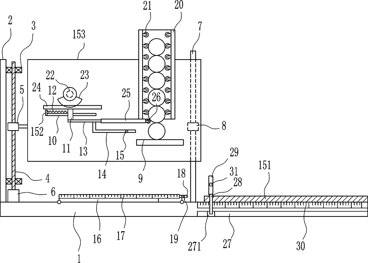
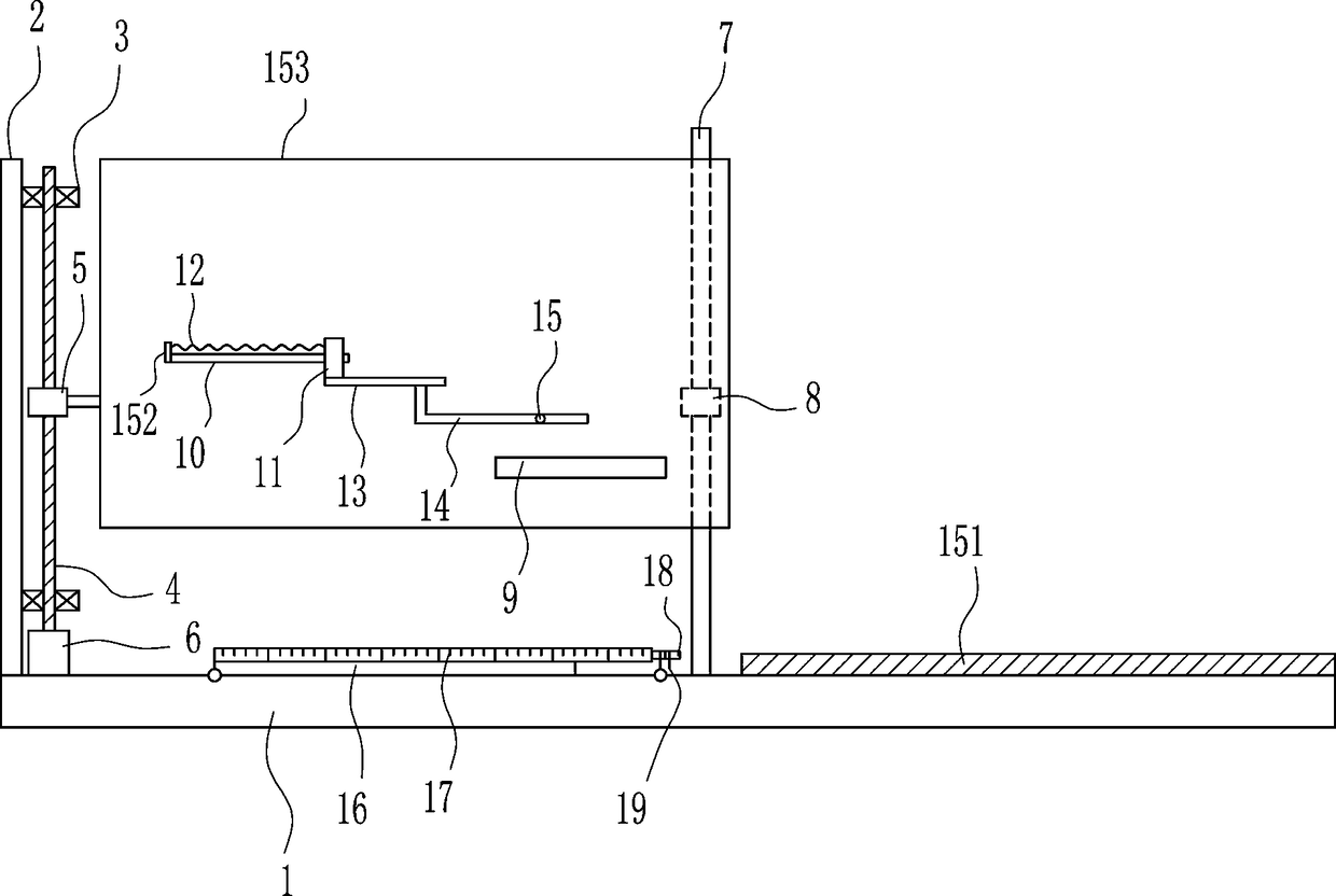
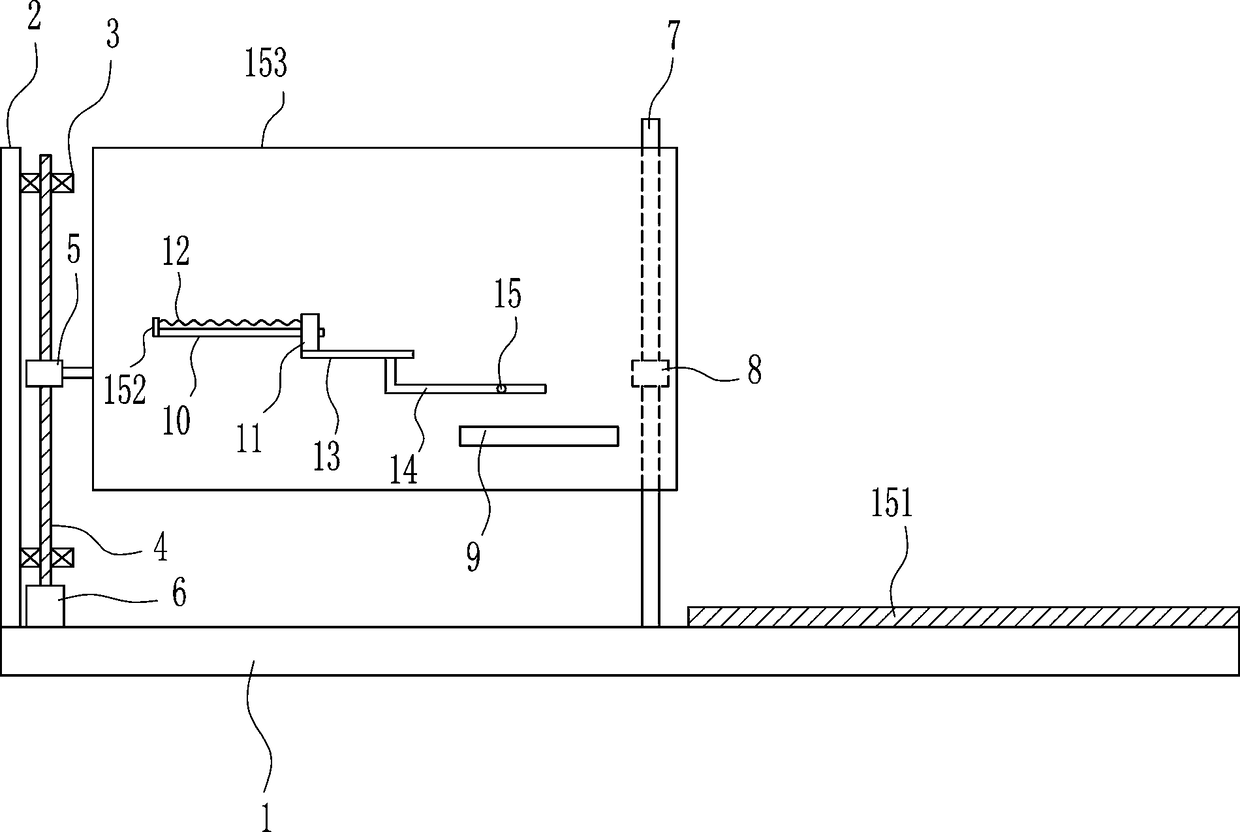
[0025] A kind of flat-throw motion demonstration equipment for physics teaching, such as Figure 1-5As shown, it includes a base 1, a mounting plate 2, a bearing seat 3, a screw rod 4, a nut 5, a servo motor 6, a first guide rail 7, a first guide sleeve 8, a placement plate 9, a first slide rail 10, a first Slide block 11, spring 12, connecting rod 13, push rod 14, first handle 15, sponge plate 151, fixed block 152 and moving plate 153, base 1 upper left part is provided with mounting plate 2, and mounting plate 2 right side up and down two The upper and lower bearing seats 3 are connected with a screw 4, and the middle part of the screw 4 is connected with a nut 5 through a threaded connection. The nut 5 cooperates with the screw 4, and the right side of the nut 5 is set. There is a moving plate 153, the upper left part of the base 1 is provided with a servo motor 6, the servo motor 6 is located on the right side of the mounting plate 2, the lower end of the screw mandrel 4 i...

Embodiment 2

[0027] A kind of flat-throw motion demonstration equipment for physics teaching, such as Figure 1-5 As shown, it includes a base 1, a mounting plate 2, a bearing seat 3, a screw rod 4, a nut 5, a servo motor 6, a first guide rail 7, a first guide sleeve 8, a placement plate 9, a first slide rail 10, a first Slide block 11, spring 12, connecting rod 13, push rod 14, first handle 15, sponge plate 151, fixed block 152 and moving plate 153, base 1 upper left part is provided with mounting plate 2, and mounting plate 2 right side up and down two The upper and lower bearing seats 3 are connected with a screw 4, and the middle part of the screw 4 is connected with a nut 5 through a threaded connection. The nut 5 cooperates with the screw 4, and the right side of the nut 5 is set. There is a moving plate 153, the upper left part of the base 1 is provided with a servo motor 6, the servo motor 6 is located on the right side of the mounting plate 2, the lower end of the screw mandrel 4 ...

Embodiment 3

[0030] A kind of flat-throw motion demonstration equipment for physics teaching, such as Figure 1-5 As shown, it includes a base 1, a mounting plate 2, a bearing seat 3, a screw rod 4, a nut 5, a servo motor 6, a first guide rail 7, a first guide sleeve 8, a placement plate 9, a first slide rail 10, a first Slide block 11, spring 12, connecting rod 13, push rod 14, first handle 15, sponge plate 151, fixed block 152 and moving plate 153, base 1 upper left part is provided with mounting plate 2, and mounting plate 2 right side up and down two The upper and lower bearing seats 3 are connected with a screw 4, and the middle part of the screw 4 is connected with a nut 5 through a threaded connection. The nut 5 cooperates with the screw 4, and the right side of the nut 5 is set. There is a moving plate 153, the upper left part of the base 1 is provided with a servo motor 6, the servo motor 6 is located on the right side of the mounting plate 2, the lower end of the screw mandrel 4 ...


PUM


Abstract

The invention relates to demonstration equipment, in particular to flat parabolic motion demonstration equipment for physics teaching and aims at solving the technical problem of providing the flat parabolic motion demonstration equipment for physics teaching, enabling a student to intuitively observe the flat parabolic motion process and improving the teaching effect. According to the technical scheme, the flat parabolic motion demonstration equipment for physics teaching comprises a base, a mounting plate, bearing blocks, a screw rod, a nut, a servo motor, a first guide rail, a first guide sleeve, a placement plate, a first sliding rail, a first sliding block and the like; the mounting plate is arranged at the left part of the upper side of the base; the bearing blocks are arranged at the upper part and the lower part of the right side of the mounting plate respectively; and the screw rod is connected between the bearing blocks on the upper side and the lower side. The flat parabolicmotion demonstration equipment for physics teaching enables the student to intuitively observe the flat parabolic motion process and improve the teaching effect. By adopting the flat parabolic motiondemonstration equipment for physics teaching, a physics teacher can continuously change the height of the placement plate, so that a small ball is thrown out from different heights, the student observes flat parabolic motion falling distances of the small ball under different heights, understanding of the student to a knowledge point is enhanced, and the teaching effect is better.

Description

technical field [0001] The invention relates to a demonstration device, in particular to a flat throw movement demonstration device for physics teaching. Background technique [0002] "Physics Teaching" is a secondary education academic journal sponsored by the Chinese Physical Society in 1978, mainly for middle school physics teachers. The goal of running the journal is to inherit the culture of physics science, communicate educational theory and physics teaching practice, and integrate physics teaching experience, and aim to maximize the quality of middle school physics teaching. [0003] Nowadays, many knowledge points in physics teaching are taught only based on the teacher's oral explanation, including the knowledge points about flat throwing motion. When there are factors, it is impossible for students to intuitively understand the knowledge point, resulting in poor teaching effect. [0004] Therefore urgently need to develop a kind of process that can make students ...

Claims


Application Information

Patent Timeline
Patent Type & Authority Applications(China)
IPC IPC(8): G09B23/10
CPCG09B23/10
Inventor 李芸华张元青姜云斐胡胜龙徐晓宇
Owner JIANGXI COLLEGE OF APPLIED TECH
Why Eureka
Try Eureka