
External bone fixing device

A bone fixation and positioning plate technology, applied in the field of medical devices, can solve the problems of large installation location limitations, large installation prestress, and no suitable installation location, etc., to reduce the pain of implantation, reduce installation prestress, and limitations sex-reducing effect

Inactive Publication Date: 2018-08-10
芜湖启泽信息技术有限公司
View PDF0 Cites 0 Cited by
  • Summary
  • Abstract
  • Description
  • Claims
  • Application Information

AI Technical Summary

Problems solved by technology

[0002] When the existing retainer is installed with a fixed bracket, the installation position is relatively limited, and there is no suitable installation position. into pain

Method used


Image

  • External bone fixing device

Examples


Embodiment Construction

[0012] The technical solutions of the present invention will be described in detail below, but the protection scope of the present invention is not limited to the examples.

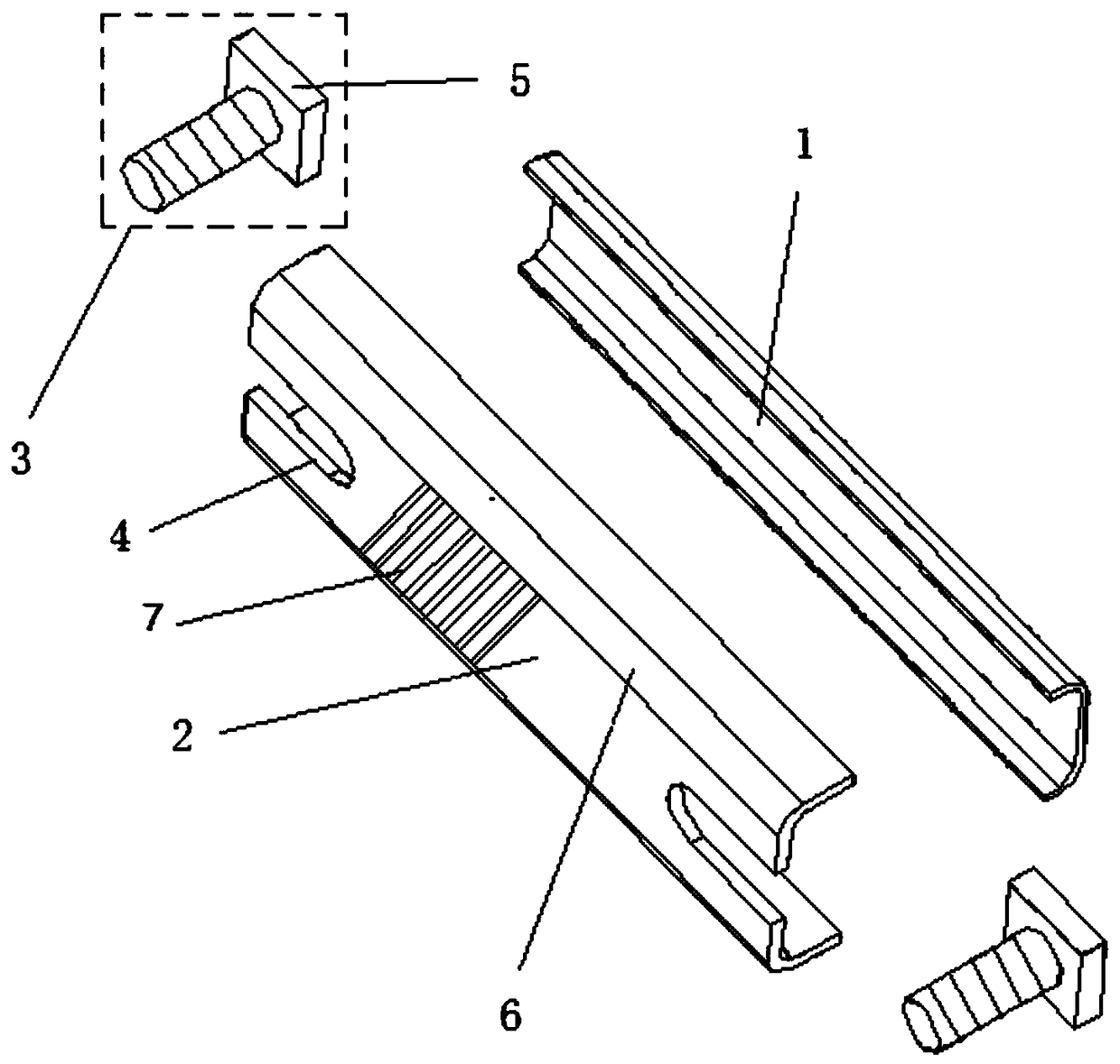
[0013] Such as figure 1 As shown, an external bone fixation device of the present invention includes a U-shaped positioning plate 1, a U-shaped guard plate 2 and bolts 3, and U-shaped grooves 4 are opened at both ends of the U-shaped guard plate 2, and U-shaped grooves 4 The width is slightly larger than the diameter of the bolt 3, the thickness of the U-shaped groove 4 of the U-shaped guard plate 2 is smaller than that of the two sides of the U-shaped guard plate 2, and the vertical distance between the two side walls of the U-shaped positioning plate 1 interferes with the width of the base 5 of the bolt 3 Cooperate, the base 5 is a quadrilateral base or a pentagonal base, the bottom surface thickness of the U-shaped positioning plate 1 is less than the side wall thickness of the U-shaped positioning pla...


PUM


Abstract

The invention discloses an external bone fixing device. The external bone fixing device comprises a U-shaped positioning plate, a U-shaped protection plate and bolts. U-shaped grooves are formed in two ends of the U-shaped protection plate respectively. The widths of the U-shaped grooves are slightly larger than the diameters of the bolts. The thicknesses of the U-shaped groove positions of the U-shaped protection plate are smaller than those of two lateral portions of the U-shaped protection plate. The vertical distance between two side walls of the U-shaped positioning plate is in interference fit with the widths of bases of the bolts. The thickness of the bottom surface of the U-shaped positioning plate is smaller than that of the side wall of the U-shaped positioning plate. The heightof the side wall of the U-shaped protection plate is smaller than that of the side wall of the U-shaped positioning plate. The U-shaped protection plate is arranged in an accommodating cavity of the U-shaped positioning plate. The external bone fixing device has the advantages that system accumulated tolerances can be adjusted through distance adjustment among the U-shaped positioning plate, the U-shaped protection plate and the bolts, mounting pre-stressing force can be reduced, and accordingly, implanting pain of patients can be relieved greatly.

Description

technical field [0001] The invention relates to a medical device, in particular to a bone fixation device. Background technique [0002] When the existing fixator is installed with a fixed bracket, the installation position is relatively limited, there is no suitable installation position, the fixed bracket is difficult to arrange, and the accumulated tolerance of the system cannot be adjusted, resulting in excessive installation prestress and increasing the patient's implant pressure. into pain. Contents of the invention [0003] Purpose of the invention: The purpose of the present invention is to provide an external bone fixation device for the shortcomings of the prior art, which is convenient to use. [0004] Technical solution: An external bone fixation device of the present invention includes a U-shaped positioning plate, a U-shaped guard plate and bolts. Both ends of the U-shaped guard plate are provided with U-shaped grooves, and the width of the U-shaped groove i...

Claims


Application Information

Patent Timeline
Patent Type & Authority Applications(China)
IPC IPC(8): A61B17/64
CPCA61B17/6425A61B2017/564
Inventor 曾伟宏
Owner 芜湖启泽信息技术有限公司
Learn More