Tire bladder mold

A capsule and mold technology, applied in tires, household appliances, other household appliances, etc., can solve the problem of uneven heating of the mold, and achieve the effect of ensuring stability and uniformity, simple structure, and ensuring uniform heating

Pending Publication Date: 2018-08-10
HIMILE MECHANICAL SCI & TECH (SHANDONG) CO LTD
View PDF0 Cites 1 Cited by
  • Summary
  • Abstract
  • Description
  • Claims
  • Application Information

AI Technical Summary

Problems solved by technology

[0007] The purpose of the present invention is to provide a tire bladder mold, which improves the problem of uneven heating of existing molds, thereby ensuring the vulcanization effect of tire products

Method used


Image

  • Tire bladder mold
  • Tire bladder mold
  • Tire bladder mold

Examples


Embodiment 1

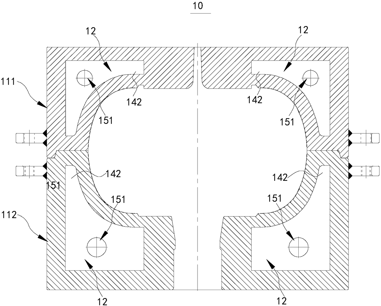
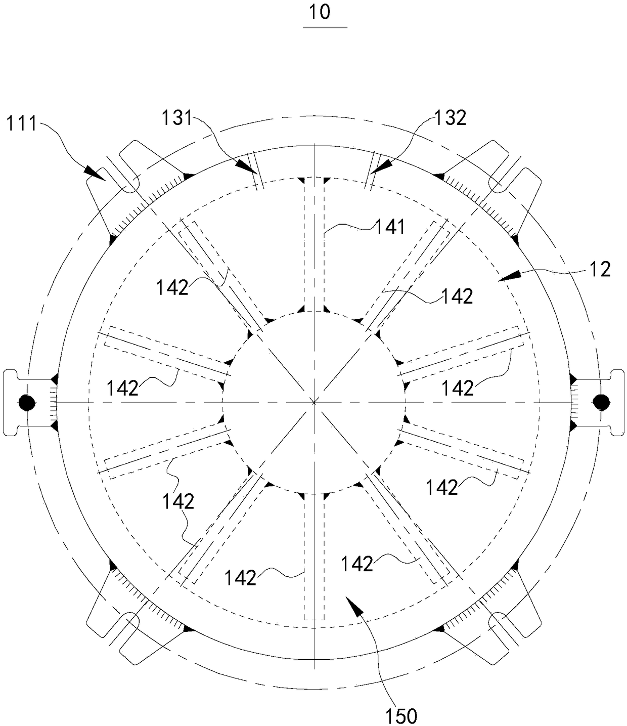
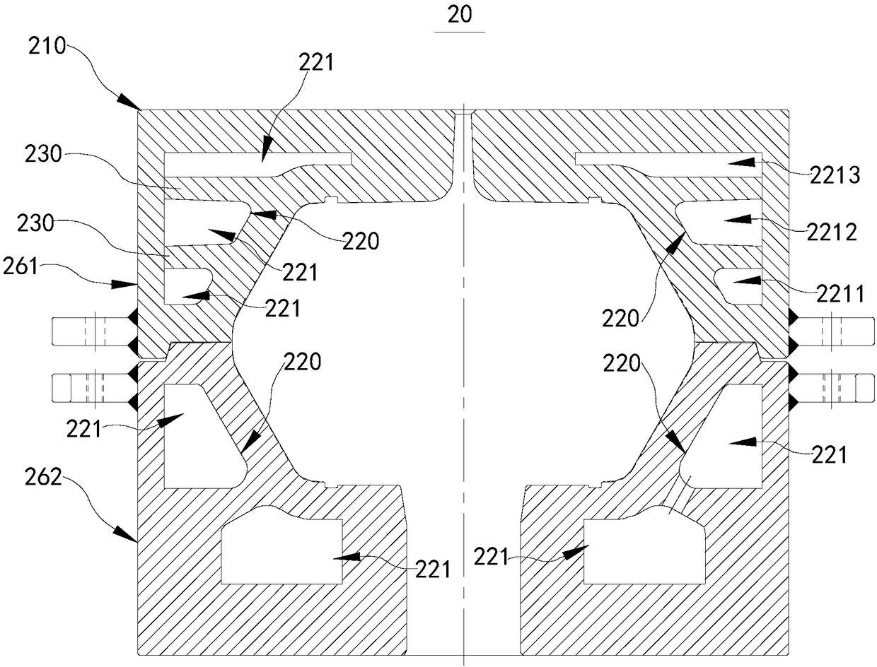
[0051] image 3 It is a schematic structural diagram of a tire bladder mold 20 provided by an embodiment of the present invention. Figure 4 for image 3 Schematic diagram of the structure from another perspective. Figure 5 for Figure 4 local schematic diagram. Please refer to Figure 3-Figure 5 , a tire bladder mold 20 includes a mold body 210 , an oil chamber cavity 220 , a horizontal plate 230 and a partition 250 .

[0052] The oil chamber cavity 220 is a hollow and airtight annular structure distributed along the circumference of the mold body 210 . The horizontal plate 230 divides the oil chamber cavity 220 into at least two annular sub-oil chambers 221 , and the plurality of sub-oil chambers 221 are distributed along the height direction of the mold body 210 . An oil inlet 241 is arranged on the side wall of the sub-oil chamber 221 near the lower end; an oil outlet 242 is arranged on the side wall of the sub-oil chamber 221 near the upper end. A communication pa...

Embodiment 2

[0085] Please refer to Figure 8 , Figure 8 A schematic structural view of the tire bladder mold 20 provided by this embodiment of the present invention.

[0086] Figure 8 A schematic diagram of the structure of the core mold 270 is shown in , and the structure of the core mold 270 is similar to that of the outer mold. The oil chamber cavity 220 of the core mold 270 is provided with a plurality of sub-oil chambers 221 from bottom to top, and adjacent sub-oil chambers 221 are communicated through communication channels 231 . Different from the outer mold, the oil inlet 241 of the sub-oil chamber 221 at the lower end of the mold body 210 is introduced from the axial direction of the center of the mold body 210; The central axial direction leads out.

[0087] The tire bladder mold 20 of the present embodiment of the present invention has at least the following advantages:

[0088] After entering from the oil inlet 241, the heating medium flows into the next sub-oil chamber...


PUM


Abstract

The invention relates to the field of tire mold structures, in particular to a tire bladder mold. The tire bladder mold comprises a mold body, an oil chamber, a cross plate and separation plates. Theoil chamber is of a hollow airtight annular structure distributed in the circumferential direction of the mold body. The cross plate divides the oil chamber into at least two annular secondary oil chambers, and the multiple secondary oil chambers are distributed in the height direction of the mold body. An oil inlet is formed in the position, close to the lower end, of the side wall of each secondary oil chamber. An oil outlet is formed in the position, close to the upper end, of the side wall of each secondary oil chamber. A communicating channel connected with the adjacent secondary oil chambers is arranged on the cross plate. The separation plates are arranged on the inner walls of the secondary oil chambers, and the separation plates are constructed to separate the secondary oil chambers. Therefore, the problem that in the prior art, heating is mostly uneven, and therefore the vulcanization effect of products is influenced is relieved.

Description

technical field [0001] The invention relates to the field of tire mold structures, in particular to a tire bladder mold. Background technique [0002] The production methods of curing bladders are mainly molding and injection. The tire bladder molds of these two modes are composed of an upper outer mold, a lower outer mold, an upper mandrel and a lower mandrel. The upper outer mold, the lower outer mold and the upper mandrel are divided into several heating spaces, and the heating medium enters the heating space to vulcanize the bladder. [0003] figure 1 It is a structural schematic diagram of the tire bladder mold 10 in the prior art. figure 2 It is a structural schematic diagram of another perspective of the figure. [0004] Please refer to figure 1 and figure 2 , as can be seen from the figure, the outer mold includes an upper outer mold 111 and a lower outer mold 112 that cooperate with each other. Further, the cylindrical upper outer mold 111 has an oil chambe...

Claims


Application Information

Patent Timeline
Patent Type & Authority Applications(China)
IPC IPC(8): B29C33/04B29C35/04B29L30/00
CPCB29D30/0606B29L2030/00
Inventor 王丽霞吴效华张任马海波鞠克峰王小凤姚远郭建智
Owner HIMILE MECHANICAL SCI & TECH (SHANDONG) CO LTD
Why Eureka
Try Eureka