Tide gauge winding and unwinding structure

A technology of tide gauge and bottom frame, which is applied in portable hoisting devices, hoisting devices, cranes, etc., can solve the problems of difficult position adjustment of tide gauges, troublesome installation of equipment, uneven retractable speed of retractable structures, etc., to achieve The effect of convenient adjustment position

Inactive Publication Date: 2018-08-10
THE FIRST INST OF OCEANOGRAPHY SOA
View PDF8 Cites 3 Cited by
  • Summary
  • Abstract
  • Description
  • Claims
  • Application Information

AI Technical Summary

Problems solved by technology

[0004] The purpose of the present invention is to provide a retractable structure of a tide gauge to solve the problems of uneven retractable speed of the retra

Method used


Image

  • Tide gauge winding and unwinding structure
  • Tide gauge winding and unwinding structure
  • Tide gauge winding and unwinding structure

Examples


Embodiment Construction

[0018] The following will clearly and completely describe the technical solutions in the embodiments of the present invention with reference to the accompanying drawings in the embodiments of the present invention. Obviously, the described embodiments are only some, not all, embodiments of the present invention. Based on the embodiments of the present invention, all other embodiments obtained by persons of ordinary skill in the art without making creative efforts belong to the protection scope of the present invention.

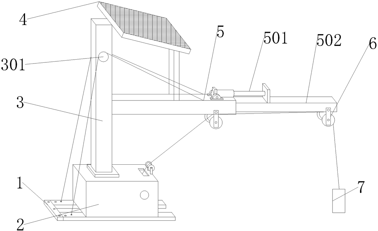
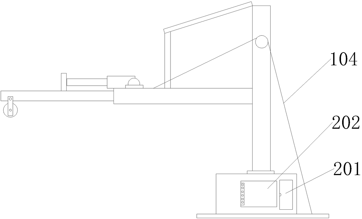
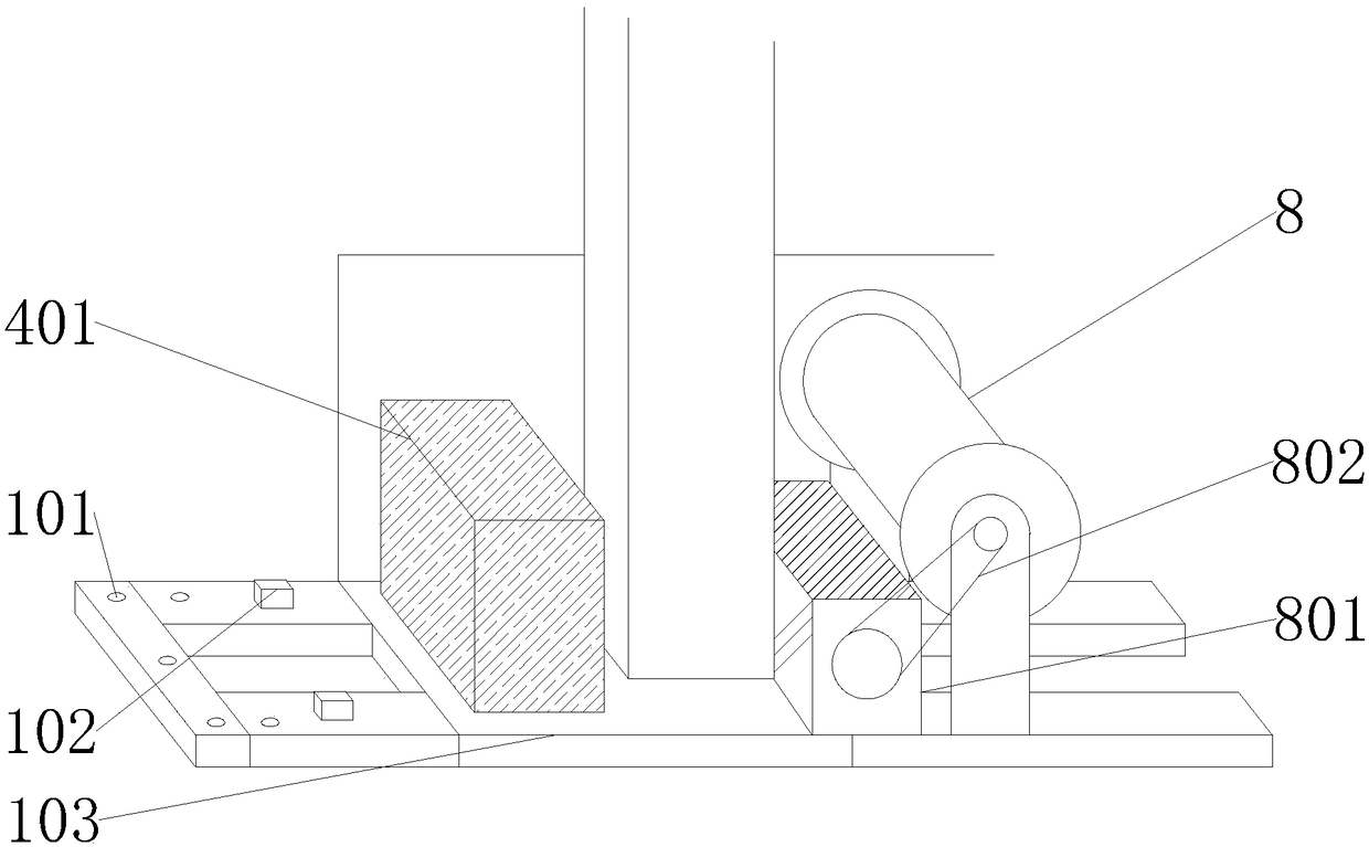
[0019] see Figure 1-3 , the present invention provides a technical solution: a tidal gauge retractable structure, including a bottom frame 1, the upper surface of the bottom frame 1 is provided with a riveting hole 101, the riveting hole 101 is set through the bottom frame 1, and the bottom frame 1 The bottom cap 103 is provided in the middle, and the bottom cap 103 is closely attached to the bottom frame 1. The top of the bottom frame 1 is provided with a ro...


PUM


Abstract

The invention discloses a tide gauge winding and unwinding structure. The tide gauge winding and unwinding structure comprises a bottom frame; the upper surface of the bottom frame is provided with ariveting hole; the riveting hole is formed in the bottom frame in a penetrating manner; the middle part of the bottom frame is provided with a bottom bearing platform which closely clings to the bottom frame; the top of the bottom frame is provided with a rope; the rope is fixedly installed at the top of the bottom frame; an equipment box is arranged at the upper surface of the bottom frame and isclosely welded together with the bottom frame; the left side of the equipment box is provided with a touch screen; and the touch screen closely clings to the left side of the equipment box. The tidegauge winding and unwinding structure can rotate under the driving of a motor by virtue of a wire winding roller arranged inside the equipment box so as to wind a connecting wire of a tide gauge or drive the motor to rotate reversely, the tide gauge can be put down, and thus the effect of winding and unwinding the tide gauge is achieved; moreover, the tide gauge is wound and unwound by driving ofthe motor, the winding and unwinding speed can be maintained to be a uniform speed, and photovoltaic power generation can be realized by virtue of a solar power generation panel arranged at the top ofan upright post, and thus an energy saving effect is achieved.

Description

technical field [0001] The invention relates to the field of retractable structures, in particular to a retractable structure for a tide gauge. Background technique [0002] The retractable structure is a device for retracting the tide gauge, through which the tide gauge can be put into the water, or the tide gauge can be retracted from the water. The purely mechanical operation saves the trouble of manual operation. [0003] However, most of the existing retractable structures are manually retractable, and the retractable speed is uneven. The existing retractable structure needs to be moved from the outside to the power supply during installation, which increases the installation process, and the installation of equipment is troublesome. , It is difficult to adjust the position when putting in the tide gauge. Contents of the invention [0004] The purpose of the present invention is to provide a retractable structure for a tide gauge to solve the problems of uneven retra...

Claims


Application Information

Patent Timeline
IPC IPC(8): B66D3/20B66D3/26B66C23/04B66C23/693
CPCB66D3/20B66C23/04B66C23/705B66D3/26
Inventor 金永德张永强徐国强王恩康
Owner THE FIRST INST OF OCEANOGRAPHY SOA
Why Eureka
Try Eureka