
Eureka
For R&D, Eureka makes reading and utilizing patents & technical documents easy.
Eureka AIR
Designed for self-driven R&D workflows. Generate viable solutions, solve complex R&D challenges, empower your innovation with AI.

Eureka Materials
Designed for material experts only. Revolutionize your material R&D, from search, analyze, to developing new materials.

TechResearch
Generate reliable direction feasibility study reports for your R&D in just a few steps.

TechSeek
Discover and master advanced knowledge NOW. Basics, ideas, possibilities, all at once.

TechMind
As an expert in R&D Theories, TechMind can generates customized viable solutions instantly.

TechRisk
Analyze your overall solution with one click, know your potential R&D risks in advance.

TechMonitor
Get weekly tech updates, stay abreast of the latest tech innovations and key insights.
Multiple turbulator heat exchanger
A technology of turbulators and trays, applied in the field of heat exchangers, can solve the problems of high cost and heavy weight
- Summary
- Abstract
- Description
- Claims
- Application Information
AI Technical Summary
Problems solved by technology
Method used
Image

Examples
Embodiment Construction
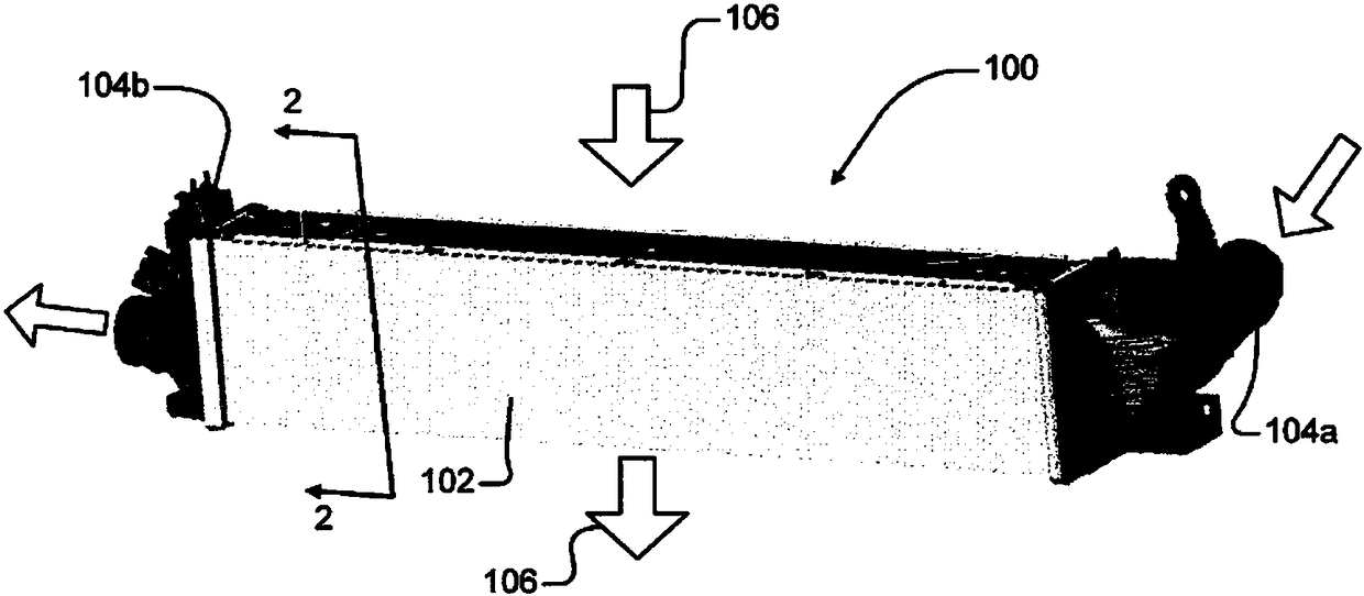
[0016] now refer to figure 1 One embodiment of the air-to-air charge air cooler (CAC) 100 of the present invention is used to cool air supplied to an intake manifold of an internal combustion engine of a motor vehicle. The CAC 100 includes a housing 102, an inlet structure 104a associated with the housing for coupling to an external conduit or hose through which compressed air from the turbocharger is delivered to the CAC. Attached to the housing 102 is an outlet structure 104b through which compressed air traveling through the CAC 100 is discharged to the intake manifold of the engine. Hot compressed air from the engine's turbocharger is directed into the CAC 100 and cooled in the CAC before being exhausted. Cooling is achieved by means of ambient airflow 106 flowing into and through the CAC 100 .
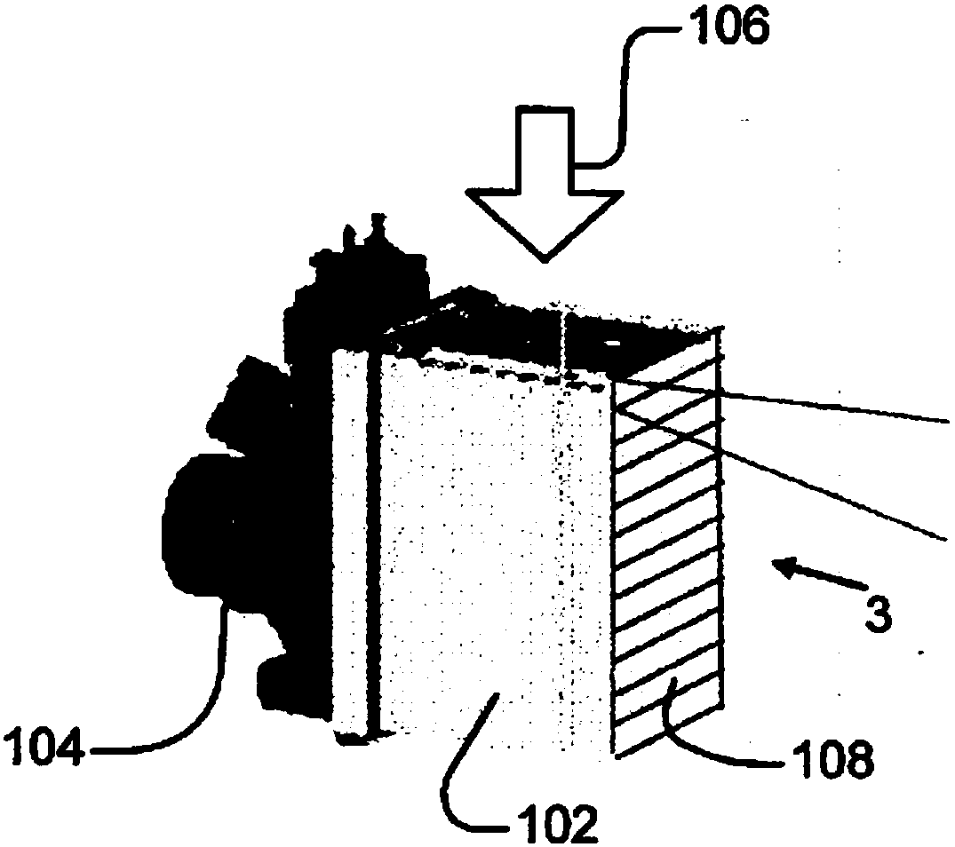
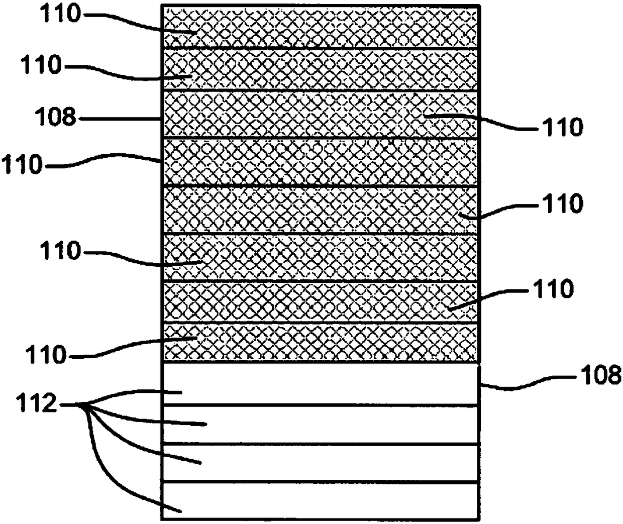
[0017] now refer to figure 2 , the housing 102 encloses a plurality of individual rectangular trays 108 through which the ambient airflow 106 flows. Each tray 108 includes a ...
PUM
 Abstract
Description
Claims
Application Information
 - R&D Engineer
- R&D Manager
- IP Professional
- Industry Leading Data Capabilities
- Powerful AI technology
- Patent DNA Extraction
Browse by: Latest US Patents, China's latest patents, Technical Efficacy Thesaurus, Application Domain, Technology Topic, Popular Technical Reports.
© 2024 PatSnap. All rights reserved.Legal|Privacy policy|Modern Slavery Act Transparency Statement|Sitemap|About US| Contact US: help@patsnap.com