Rigid-flexible coupling sliding block and movement platform

A technology of rigid-flexible coupling and slider, which is applied in the direction of linear motion bearings, bearings, shafts and bearings, can solve problems such as frictional dead zones, achieve the effects of reducing vibration and improving control bandwidth

Active Publication Date: 2018-08-10
GUANGDONG UNIV OF TECH
View PDF7 Cites 7 Cited by
  • Summary
  • Abstract
  • Description
  • Claims
  • Application Information

AI Technical Summary

Problems solved by technology

[0007] In order to solve the friction dead zone problem of the mechanical contact kinematic pair, the present invention proposes to transform the existing mechanical contact linear guide rail slider into a rigid-flexible coupling slider, so that the structure for realizing the rigid-flexible coupling motion is more compact without changing the working platform form, easier to promote

Method used


Image

  • Rigid-flexible coupling sliding block and movement platform
  • Rigid-flexible coupling sliding block and movement platform

Examples


Embodiment Construction

[0019] The accompanying drawings are for illustrative purposes only, and should not be construed as limitations on this patent; in order to better illustrate this embodiment, certain components in the accompanying drawings will be omitted, enlarged or reduced, and do not represent the size of the actual product; for those skilled in the art It is understandable that some well-known structures and descriptions thereof may be omitted in the drawings. The positional relationship described in the drawings is for illustrative purposes only, and should not be construed as a limitation on this patent.

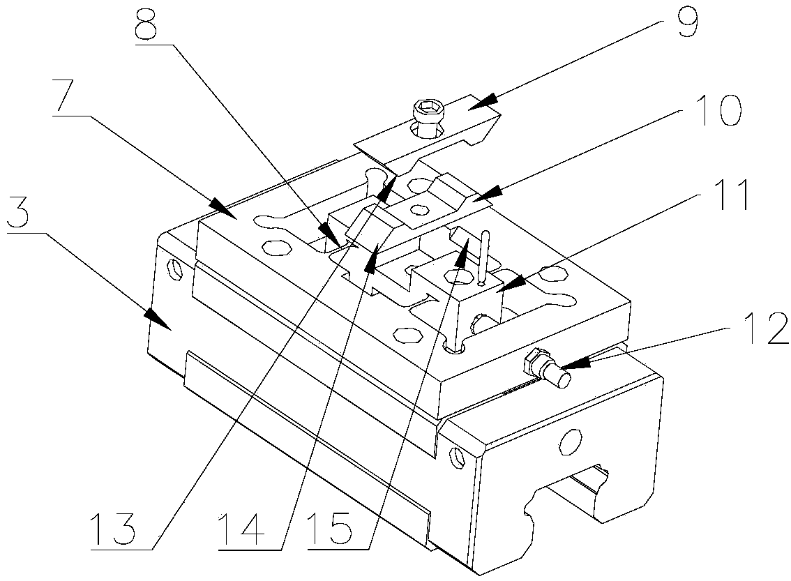
[0020] like figure 1 As shown, a rigid-flexible coupling slider includes: a sliding part 3 , a rigid frame 7 mounted on the sliding part 3 , and a guide block 11 connected to the rigid frame 7 through a flexible hinge group 8 .

[0021] Preferably, the rigid-flexible coupling slider further includes a tension adjustment mechanism for deforming the rigid frame. The tension adjusting ...


PUM


Abstract

The invention discloses a rigid-flexible coupling sliding block. The sliding block comprises a sliding component, a rigid frame installed on the sliding component, a guide block connected with the rigid frame through a flexible hinge set and a tension force adjustment mechanism enabling the rigid frame to generate deformation. A low-rigidity mode can be adopted in a tiny displacement mode and at the movement tail end, and precise compensation of tiny displacement and errors is realized through elastic deformation; and in a high-speed movement stage, a high-rigidity mode is adopted, the vibration of the component in the movement process is reduced, and the control bandwidth is broadened.

Description

technical field [0001] The invention relates to the technical field of high-speed precision motion control, and more specifically, to a rigid-flexible coupling slider. Background technique [0002] In the field of high-speed precision motion control, the motion mechanism based on the mechanical contact motion pair is affected by the friction of the guide rail and the elastic vibration of the working platform, and the accuracy can only reach the micron level. In the case of higher precision requirements, the industry needs to use air floatation, magnetic levitation and static pressure guide rails to reduce or even eliminate the influence of friction. The cost is high and the requirements for the use environment are high, so it is not suitable for electronic manufacturing occasions with large quantities and a wide range. However, Moore's Law in the electronics manufacturing industry (when the price remains constant, the number of components that can be accommodated on an integ...

Claims


Application Information

Patent Timeline
Patent Type & Authority Applications(China)
IPC IPC(8): F16C29/00
CPCF16C29/004
Inventor 杨志军熊少旺陈新李乾
Owner GUANGDONG UNIV OF TECH
Why Eureka
Try Eureka