Gas pressure reducing device

A decompression device and gas technology, applied in the direction of gas/liquid distribution and storage, pipeline system, mechanical equipment, etc., can solve the problems of inability to control gas pressure, achieve the effect of improving work efficiency, easy disassembly and fixing

Inactive Publication Date: 2018-08-10
湖州诺诚低温设备有限公司
View PDF0 Cites 0 Cited by
  • Summary
  • Abstract
  • Description
  • Claims
  • Application Information

AI Technical Summary

Problems solved by technology

[0004] In view of this, what this application is to solve is the technical problem that

Method used


Image

  • Gas pressure reducing device
  • Gas pressure reducing device

Examples


Embodiment Construction

[0021] The implementation of the present application will be described in detail below with reference to the accompanying drawings and examples, so as to fully understand and implement the implementation process of how the present application uses technical means to solve technical problems and achieve technical effects.

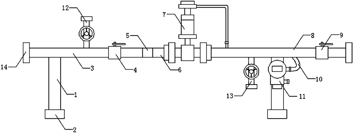
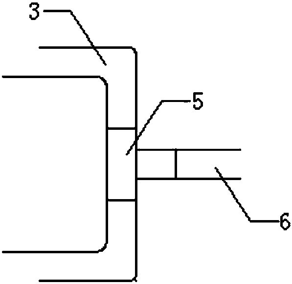
[0022] Such as Figure 1-2 As shown, a gas decompression device of the present invention includes: two support bases 1, an air inlet pipe 3 and an air outlet pipe 8, the bottom ends of the two support bases 1 are fixedly provided with fixing devices, and the top end of one of the support bases 1 It is fixedly connected with the bottom of one end of the intake pipe 3, and the middle part of the intake pipe 3 is provided with an intake pipe regulating valve 4, and the other end of the intake pipe 3 is fixedly connected with one end of the connecting pipe 6 through the connecting piece 5, and the other end of the connecting pipe 6 is connected to the reducing va...


PUM


Abstract

The invention discloses a gas pressure reducing device. The gas pressure reducing device comprises two supporting seats, gas inlet pipes and a gas outlet pipe. Fixing devices are fixedly arranged at the bottom ends of the two supporting seats correspondingly. The top end of one of the supporting seats is fixedly connected with the bottoms of one ends of the gas inlet pipes. The middles of the gasinlet pipes are provided with gas inlet pipe adjusting valves. The other ends of the gas inlet pipes are fixedly connected with one end of a connecting pipe through a connecting piece. The other end of the connecting pipe is fixedly connected with a gas inlet of a pressure reducing valve. According to the scheme, the gas pressure in a pipeline is conveniently detected through an arranged pressuredetection device, and the situation that the gas pressure fluctuation range after the pressure is reduced is large, the pressure of the gas cannot be controlled accurately, and harm is easily caused is prevented; the pressure reducing device is conveniently mounted through the arranged fixing devices, and dismounting and fixing are convenient; and the two gas inlet pipes are arranged, when one ofthe gas inlet pipes needs to be replaced or maintained, the other gas inlet pipe is used, and the gas pressure reducing device can always be in a working state.

Description

technical field [0001] The present application belongs to the technical field of gas decompression, and in particular relates to a gas decompression device. Background technique [0002] The gas decompression device in the prior art generally only includes an inlet pipe, a pressure reducing valve, a flow meter and an outlet pipe. The gas decompression device generally only has one intake pipe, and when one of the intake pipes needs to be replaced or repaired, the gas decompression device will be in a maintenance state and cannot work, which reduces the work efficiency. [0003] Therefore, in order to further improve the working efficiency of gas decompression, it is necessary to provide a gas decompression device. Contents of the invention [0004] In view of this, what the present application intends to solve is the technical problem that the pressure of the gas cannot be accurately controlled in the conventional technology. The invention provides a gas decompression de...

Claims


Application Information

Patent Timeline
IPC IPC(8): F17D3/01F17D1/04
CPCF17D3/01F17D1/04
Inventor 汤国强
Owner 湖州诺诚低温设备有限公司
Why Eureka
Try Eureka