Disassemble laser cutting knife rest structure

A laser cutting and laser cutting machine technology, applied in laser welding equipment, welding equipment, metal processing equipment, etc., can solve the problems of inability to rotate and adjust, and the fixed structure of the knife holder cannot be disassembled and separated, so as to enhance the flexibility of use, Easy to fix and remove, easy to remove and install

Inactive Publication Date: 2018-03-20
SHIYAN YANHEXING BODY SYST
View PDF0 Cites 0 Cited by
  • Summary
  • Abstract
  • Description
  • Claims
  • Application Information

AI Technical Summary

Problems solved by technology

[0005] In order to solve the above technical problems, the present invention provides a detachable laser cutting knife holder structure to solve the problem t

Method used


Image

  • Disassemble laser cutting knife rest structure
  • Disassemble laser cutting knife rest structure
  • Disassemble laser cutting knife rest structure

Examples


Embodiment

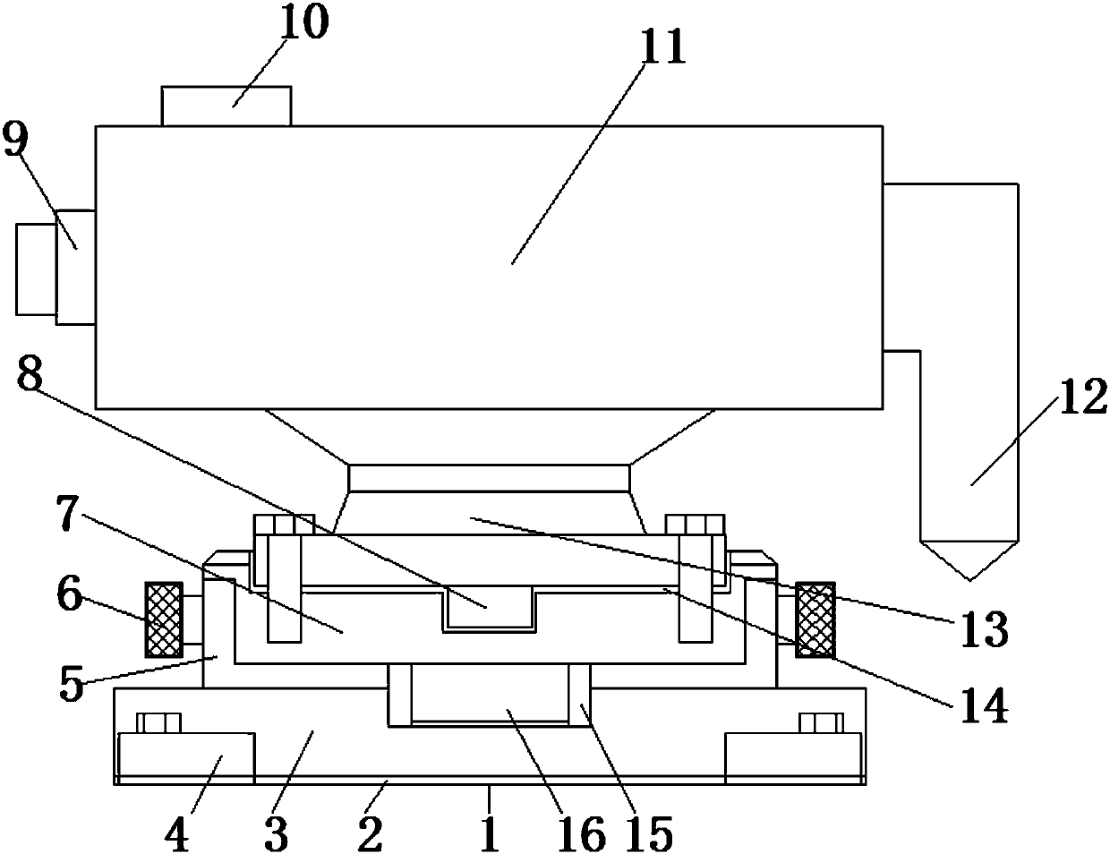
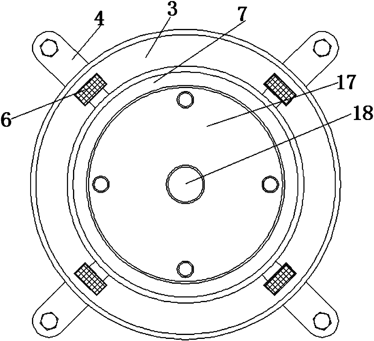
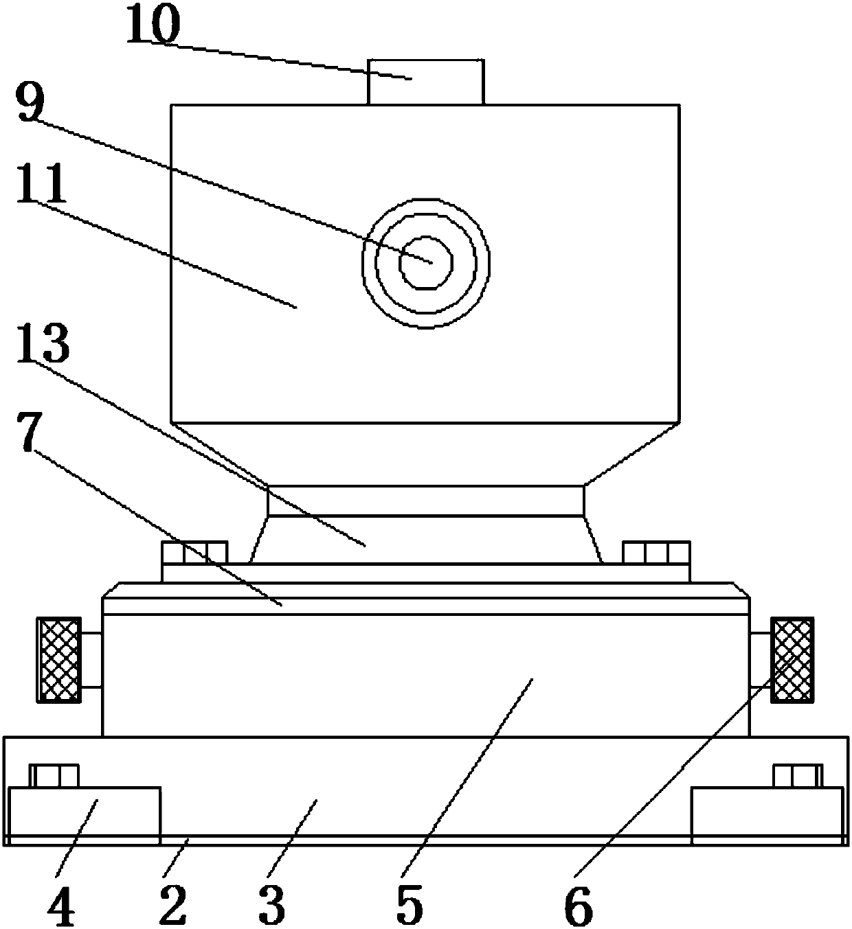
[0022] as attached figure 1 to attach Figure 4 Shown:

[0023] The present invention provides a detachable laser cutting tool holder structure, which includes a device body 1, a protective fixed pad 2, a fixed base plate 3, a fixed raised bar 4, a fixed sleeve 5, an adjustment knob 6, a rotating fixed plate 7, a raised Guide column 8, power socket 9, switch button 10, laser cutting machine 11, laser cutting head 12, connection base 13, spacer rubber layer 14, bearing 15, fixed raised column 16, limit installation groove 17 and guide fixing hole 18. The bottom of the device body 1 is provided with a fixed substrate 3, and the bottom surface of the fixed substrate 3 is provided with a protective fixed pad 2; the outer circular array of the bottom circumference of the fixed substrate 3 has four fixed raised strips 4, and the fixed raised strips 4. The outer ends are all provided with installation holes; the center of the top of the fixed base plate 3 is provided with a fixed s...


PUM


Abstract

The invention provides a detachable laser cutting tool holder structure, comprising a limit installation groove and a guide fixing hole, a fixing base plate is arranged at the bottom of the device body, and a protective fixing pad is arranged on the bottom surface of the fixing base plate; the fixing base plate is provided with a protective fixing pad; There are four fixed protruding strips in the outer annular array of the bottom circumference, and the outer ends of the fixed protruding strips are all provided with mounting holes; the center of the top of the fixed base plate is provided with a fixed sleeve, and the annular array above the outer circumference of the fixed sleeve has four adjustment knobs A bearing is installed in the inner center of the fixed sleeve, and the rotating fixed disk is fixedly installed on the top of the fixed sleeve; the center of the bottom of the rotating fixed disk is provided with a fixed convex column inserted into the bearing. The arrangement of the rotating fixed plate of the present invention is beneficial to changing the position of the laser cutting head by rotating the laser cutting machine, and can be locked by adjusting the knob when it is rotated to an appropriate position, and at the same time, the top is connected with the laser cutting machine by bolts, which is convenient for disassembly and installation .

Description

technical field [0001] The invention belongs to the technical field of laser cutting, and in particular relates to a detachable laser cutting tool holder structure. Background technique [0002] The material to be cut is irradiated with a high-power-density laser beam, so that the material is quickly heated to the vaporization temperature, and evaporates to form holes. As the beam moves to the material, the holes continuously form a narrow (such as about 0.1mm) slit. Finish cutting the material. Laser cutting is the use of a focused high-power-density laser beam to irradiate the workpiece, so that the irradiated material is rapidly melted, vaporized, ablated or reached the ignition point, and at the same time the molten material is blown away by the high-speed airflow coaxial with the beam, so as to realize the cutting of the workpiece. open. Laser cutting is one of the thermal cutting methods. [0003] Based on the above, the inventors found that the fixed structure of t...

Claims


Application Information

Patent Timeline
IPC IPC(8): B23K26/38B23K26/70
CPCB23K26/38B23K26/702
Inventor 陈新红陈世伦王斌梁文清
Owner SHIYAN YANHEXING BODY SYST
Why Eureka
Try Eureka