
Fixing fixture for mechanical mold machining

A technology for mold processing and fixing fixtures, applied in the direction of workpiece clamping devices, manufacturing tools, etc., can solve the problem of low fixing strength, achieve the effects of easy fixing and disassembly, enhanced fixing effect, and avoid damage

Inactive Publication Date: 2020-05-22
平湖市超凯科技有限公司
View PDF1 Cites 0 Cited by
  • Summary
  • Abstract
  • Description
  • Claims
  • Application Information

AI Technical Summary

Problems solved by technology

[0004] The object of the present invention is to provide a fixing fixture for mechanical mold processing, to solve the problem of low fixing strength only through the friction between the lead screw and the desktop, which is proposed in the above background.

Method used


Image

  • Fixing fixture for mechanical mold machining
  • Fixing fixture for mechanical mold machining
  • Fixing fixture for mechanical mold machining

Examples


Embodiment Construction

[0021] The technical solutions in the embodiments of the present invention will be clearly and completely described below in conjunction with the accompanying drawings in the examples of the present invention. Obviously, the described embodiments are only some of the embodiments of the present invention, not all of them. Based on the embodiments of the present invention, all other embodiments obtained by persons of ordinary skill in the art without creative efforts fall within the protection scope of the present invention.

[0022] see Figure 1-4 , the present invention provides a technical solution:

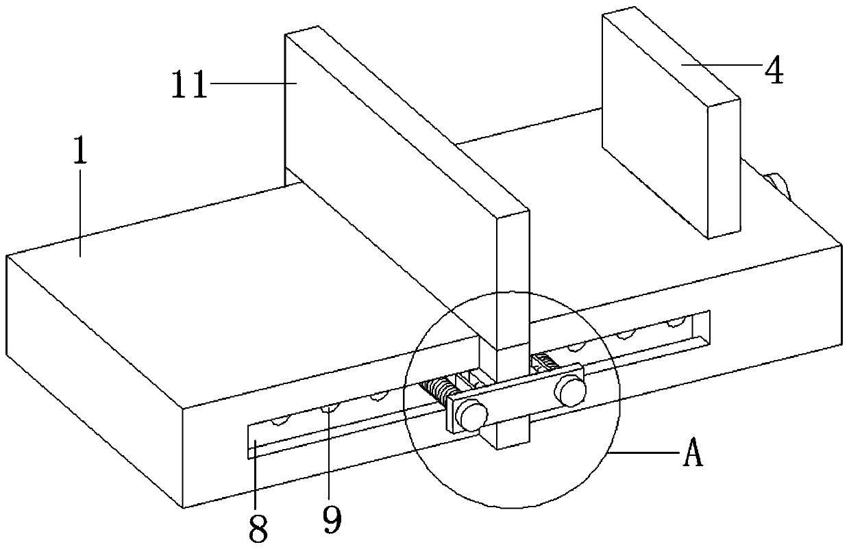
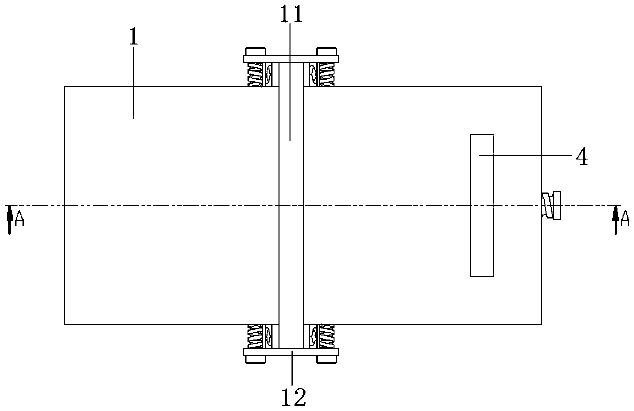
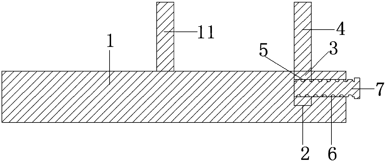
[0023] Such as Figure 1 to Figure 3 As shown, a fixing fixture for mechanical mold processing includes a mounting base 1, and the top of the mounting base 1 is provided with a mounting groove 2, and the mounting groove 2 is arranged near the top edge of the mounting base 1, and the center of the top of the mounting groove 2 is located on the mounting base. On the center line...


PUM


Abstract

The invention discloses a fixing fixture for mechanical mold machining. The fixing fixture comprises a mounting base. The top end of the mounting base is provided with a mounting groove. A connectingplate is inserted in the mounting groove. A fixed plate is fixed to the top end of the connecting plate. The center of the side face of the connecting plate is provided with a through screw hole. Thecenter of the sidewall of the mounting groove is provided with a connecting screw hole. The connecting screw hole penetrates through the side face of the mounting base. A mounting screw rod is in threaded connection with the interiors of the connecting screw hole and the through screw hole. The two opposite side faces of the mounting base are provided with sliding grooves. The sliding grooves areprovided with fixing screw holes. A sliding block is slidably connected to the interior of each sliding groove. The end of each sliding block is fixedly connected with a mounting plate. An adjusting plate is fixed to the top ends of the mounting plates. A limiting mechanism is arranged on the outer side face of each mounting plate. Each limiting mechanism comprises a main board and limiting screwrods. The side face of each main board is symmetrically provided with two matched screw holes. The inner side face of each main board is symmetrically and fixedly provided with two clamping plates, pressure springs are fixed to the centers of the side faces of the clamping plates, and movable plates are fixed to the ends of the pressure springs.

Description

technical field [0001] The invention relates to the field of mechanical mold processing, in particular to a fixing fixture for mechanical mold processing. Background technique [0002] Fixtures are tools used to fasten workpieces during processing and fix parts in corresponding positions. Fixture technology is developing in the direction of high precision, high efficiency, modules, combinations, general purpose, and economy. Fixtures are also called fixtures. In a broad sense , in any process in the process, the device used to install the workpiece conveniently and safely can be called a fixture, such as welding fixtures, inspection fixtures, assembly fixtures, mold fixtures, etc., which need to be used during machining. For fixing, with the development of machining technology, the fixing fixtures for mechanical mold processing have also been technically improved. [0003] At present, the Chinese patent with the application number CN201720916988.5 discloses a fixing fixture...

Claims


Application Information

Patent Timeline
IPC IPC(8): B25B11/00
CPCB25B11/00
Inventor 陈礼成
Owner 平湖市超凯科技有限公司
Learn More