A method for testing real-time dynamic stress of disc-type tie-rod combined rotors

A real-time dynamic, test method technology, applied in the direction of measuring force, measuring device, instrument, etc., can solve problems such as not being well solved, and achieve the effect of simple structure, overcoming inaccuracy, and easy installation

Active Publication Date: 2020-07-28
XI AN JIAOTONG UNIV
View PDF6 Cites 0 Cited by
  • Summary
  • Abstract
  • Description
  • Claims
  • Application Information

AI Technical Summary

Problems solved by technology

[0002] The rotor system in the rotating machinery system is the core power unit of the power machinery. It is often in a high-speed, heavy-load working state, and the actual force is complex and changeable. The real-time monitoring of the stress and strain of the tie-rod composite rotor system is mainly based on static testing. The real-time testing of the stress and strain of the rotating mechanical rotor structure under the actual working condition has not been well resolved. For the open composite rotor structure, It is an effective method to carry out stress test by using wireless test scheme, but for the combined rotor structure with closed structure, and most of them are made of metal material, when it is necessary to test the dynamic stress on the surface of internal parts, the wireless test signal will be affected by the metal material. It is difficult to reflect the stress and strain of the actual working state of the component due to the shielding effect

Method used


Image

  • A method for testing real-time dynamic stress of disc-type tie-rod combined rotors

Examples


Embodiment Construction

[0024] The present invention is further described below in conjunction with accompanying drawing:

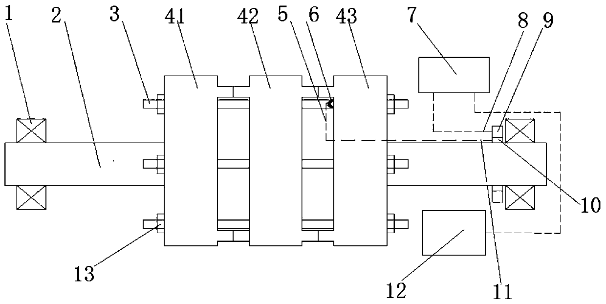
[0025] see figure 1 ,

[0026] A method for testing the real-time dynamic stress of a disc-type tie-rod combined rotor, the disc-type tie-rod combined rotor includes a rotor 2, a tie rod 3, a left disc 41, a middle disc 42, and a right disc 43; the center of one side of the left disc 41 is vertically arranged There is a rotor 2, and the center of one side of the right disc 43 is vertically provided with the rotor 2, the side of the left disc 41 and the right disc 43 without the rotor 2 is arranged oppositely, the middle disc 42 is arranged between the left disc 41 and the right disc 43, and the left disc 41. The middle disk 42 and the right disk 43 are set concentrically; the left disk 41, the middle disk 42 and the right disk 43 are all provided with tie rod holes, and the tie rods 3 pass through the tie rod holes in turn to connect the three disks;

[0027] The method for te...


PUM


Abstract

The invention discloses a disc pull rod composite rotor real-time dynamic stress test method. The real-time dynamic stress test is performed on the rotor, the pull rod and the wheel disc of the disc pull rod composite rotor system under the actual working state by using a conductive slip ring, electric resistance stress gauges and a data acquisition system. The electric resistance stress gauges are adhered on the stress concentration position or the fatigue fracture position and other critical positions of the disc pull rod composite rotor system, the conductive slip ring is installed on the position close to the bearing of the rotating shaft of the rotor, and the stress signals generated by the electric resistance stress gauges are transmitted to the data acquisition system through the conductive slip ring so that real-time monitoring and early warning of the stress-strain of the critical positions of the class of rotating mechanical rotor system can be realized. The method is suitable for the field of the rotating mechanical stress test, and particularly suitable for the real-time stress test of the composite rotor system of the enclosed structure.

Description

technical field [0001] The invention belongs to the technical field of rotating machinery testing, and in particular relates to a method for testing real-time dynamic stress of a disk-type tie-rod combination type rotor. Background technique [0002] The rotor system in the rotating machinery system is the core power unit of the power machinery. It is often in a high-speed, heavy-load working state, and the actual force is complex and changeable. The real-time monitoring of the stress and strain of the tie-rod combination rotor system is mostly based on static testing. The real-time testing of the stress and strain of the rotor structure of the rotating machine under the actual working condition has not been well solved. For the open combined rotor structure, It is an effective method to use the wireless test scheme to carry out the stress test. For the combined rotor structure with closed structure, and most of them are made of metal, when it is necessary to test the dynami...

Claims


Application Information

Patent Timeline
Patent Type & Authority Patents(China)
IPC IPC(8): G01L1/22
CPCG01L1/22
Inventor 刘恒王南山许志东戚社苗刘意田桂斌
Owner XI AN JIAOTONG UNIV
Why Eureka
Try Eureka