Droplet control detector and working method thereof

A technology for controlling detection and working methods, applied in the field of microfluidics, can solve the problems of high production cost, need to improve droplet control accuracy, complex structure, etc., and achieve the effect of efficient and precise control

Active Publication Date: 2018-02-02
BOE TECH GRP CO LTD
View PDF6 Cites 35 Cited by
  • Summary
  • Abstract
  • Description
  • Claims
  • Application Information

AI Technical Summary

Problems solved by technology

[0003] However, the existing microfluidic devices have the following disadvantages: the structure is relatively complex, the production cost is high, and the precision of droplet control needs to be improved

Method used


Image

  • Droplet control detector and working method thereof
  • Droplet control detector and working method thereof
  • Droplet control detector and working method thereof

Examples


Embodiment Construction

[0059] In order to make the technical problems, technical solutions and advantages to be solved by the embodiments of the present invention clearer, the following will describe in detail with reference to the drawings and specific embodiments.

[0060] The embodiments of the present invention aim at the problems that the structure of the microfluidic device in the prior art is relatively complex, the production cost is high, and the accuracy of droplet control needs to be improved, and a droplet control detection device and its working method are provided, which can Achieve efficient and precise droplet control.

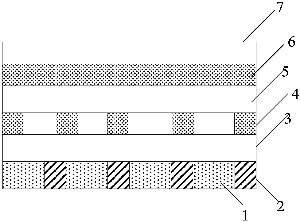
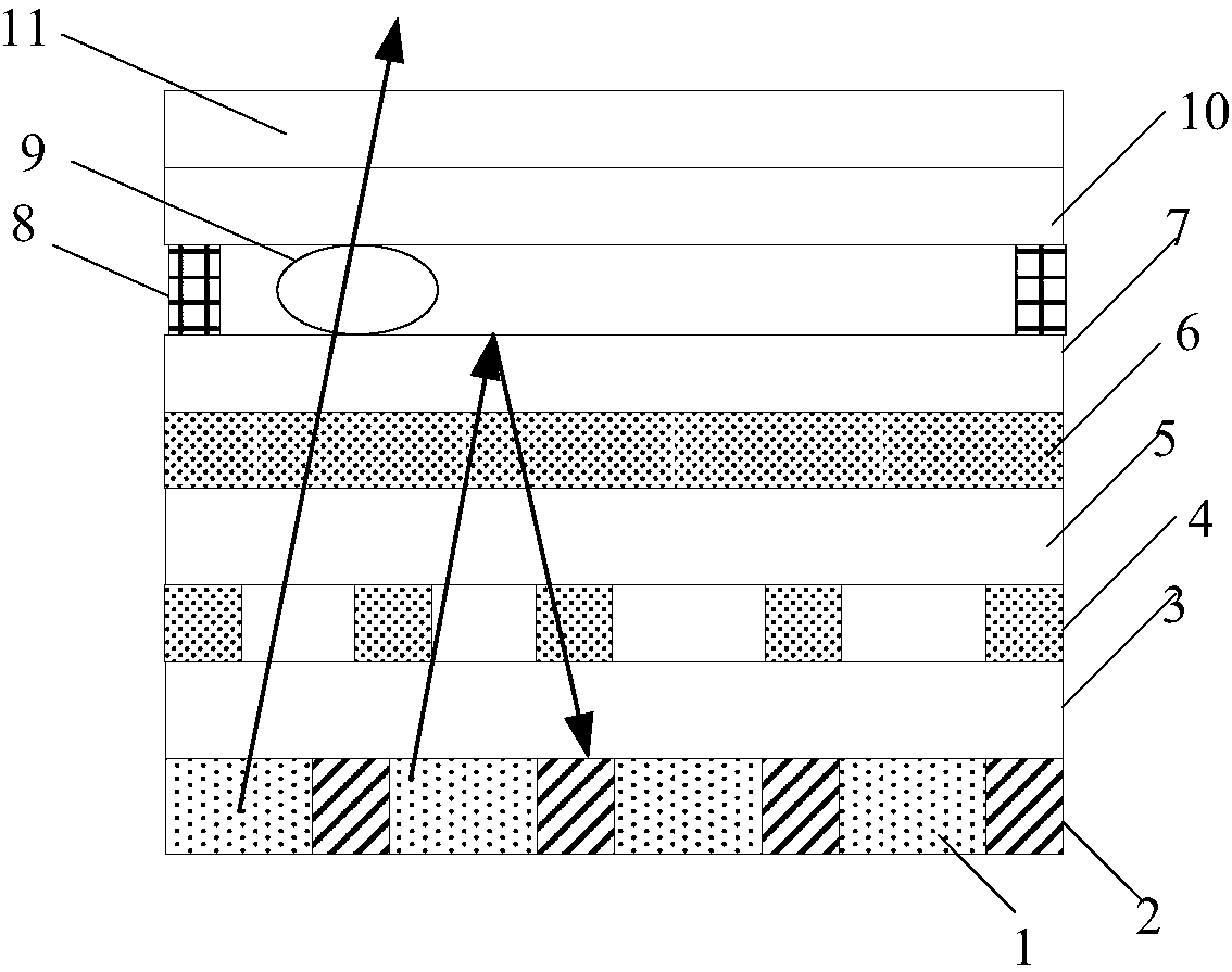
[0061] An embodiment of the present invention provides a droplet control detection device, including:

[0062] light source;

[0063] a first electrode and a second electrode, an electric field capable of driving droplet movement can be formed between the first electrode and the second electrode;

[0064] The liquid droplet located on the light emitting side of the...


PUM


Abstract

The invention provides a droplet control detector and a working method thereof, and belongs to the technical field of microfluidics. The droplet control detector comprises: a light source; a first electrode and a second electrode, wherein an electric field for driving a droplet to move is formed between the first electrode and the second electrode; the droplet positioned at the light emitting sideof the light source, wherein the the electric field between the first electrode and the second electrode drives the droplet to move when an electrical signal is applied to the first electrode and thesecond electrode; a photodetection structure capable of detecting lights emitted by the light source and reflected by the droplet and obtaining droplet information according to the detection result;and a processing circuit used for controlling the electric signal applied to the first electrode and the second electrode according to the droplet information. The droplet control detector can realizehighly-effective and accurate droplet control.

Description

technical field [0001] The invention relates to the field of microfluidic technology, in particular to a droplet control detection device and a working method thereof. Background technique [0002] Microfluidics (Microfluidics) refers to the science and technology involved in the use of micropipes (tens to hundreds of microns in size) to process or manipulate tiny fluids (nanoliters to attic liters in volume). , fluid physics, microelectronics, new materials, emerging interdisciplinary disciplines of biology and biomedical engineering. Because of the characteristics of miniaturization and integration, microfluidic devices are usually called microfluidic chips, also known as lab on a chip (Lab on a Chip) and micro-Total Analytical System (micro-Total Analytical System). The early concept of microfluidics can be traced back to the gas chromatograph produced on silicon wafers by photolithography in the 1870s, and then developed into microfluidic capillary electrophoresis and m...

Claims


Application Information

Patent Timeline
Patent Type & Authority Applications(China)
IPC IPC(8): B01L3/00
CPCB01L3/5027B01L3/50273B01L2400/0415B01L2200/143B01L2300/0663B01L3/502784B01L2300/0645B01L2300/165B01L2400/0427H10K59/60H10K50/844B01L2200/10B81B7/02G01N27/44791G01N27/44721B81B2201/058B81B2203/04B81B2203/0315B81B2203/055B01L3/502715
Inventor 丁小梁董学王海生刘英明曹学友郭玉珍张平王鹏鹏韩艳玲郑智仁邓立凯李扬冰
Owner BOE TECH GRP CO LTD
Why Eureka
Try Eureka