Drop hammer type dynamic impact testing machine and testing method thereof
A dynamic impact and testing machine technology, applied in the direction of measuring devices, instruments, scientific instruments, etc., can solve the problems that the roadway cannot be used normally, cannot fully meet the requirements of deep roadway support, bolt fracture, slip and other problems, and achieve a novel structure. , the effect of strong functionality and high economic value
Pending Publication Date: 2018-08-10
NORTHEASTERN UNIV
View PDF0 Cites 27 Cited by
- Summary
- Abstract
- Description
- Claims
- Application Information
AI Technical Summary
Problems solved by technology
Based on the traditional prestressed bolt support system, it cannot adapt to such large deformations, and the anchor bolts will break, slip and other failure forms, resulting in damage to the side of the roadway, bottom heave, roof fall, etc.
Make the roadway unusable
[0004] In view of the large deformation of deep roadways, the conventiona
Method used
View moreImage
Smart ImageViewing Examples

Examples
 PUM
 Abstract
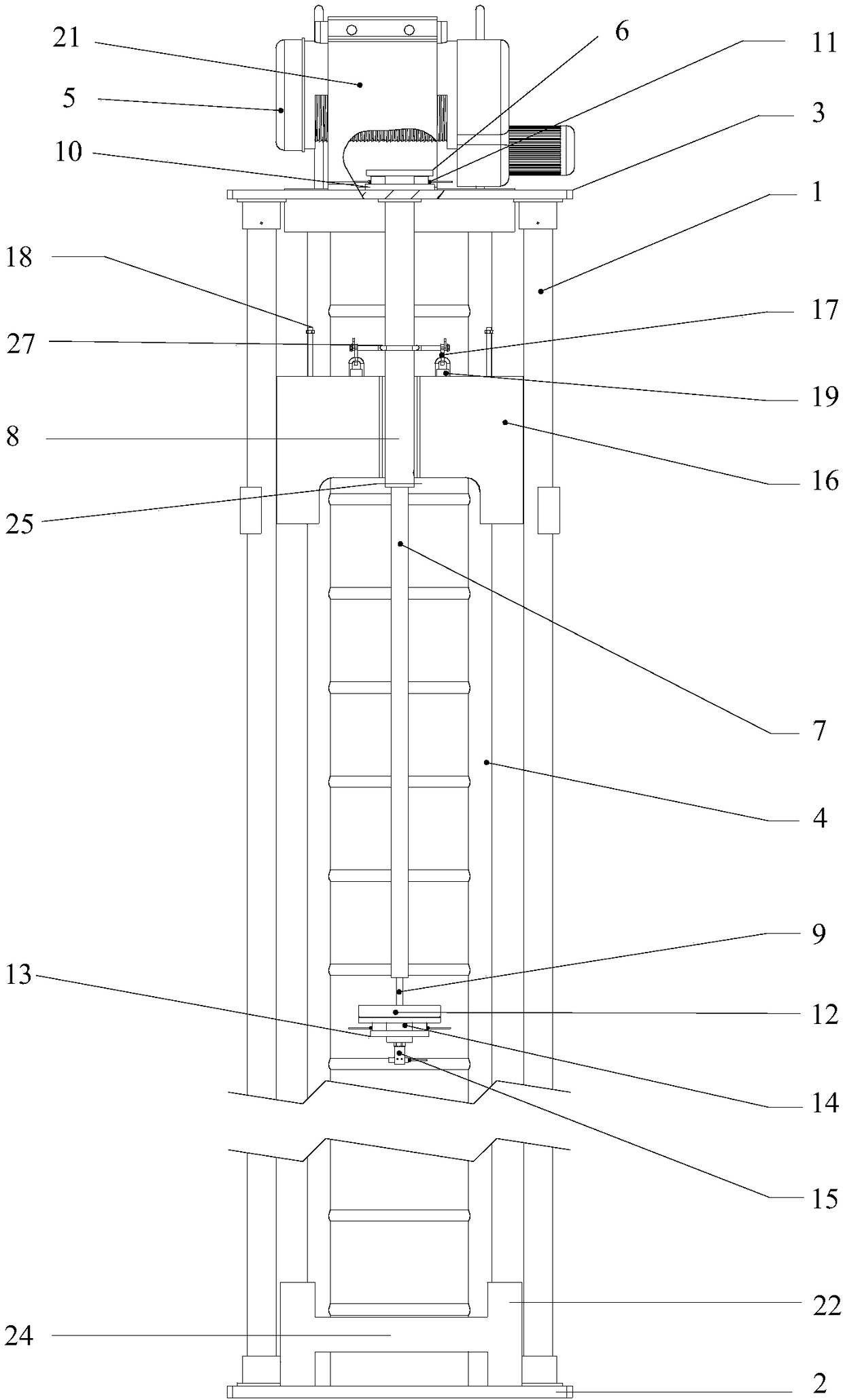
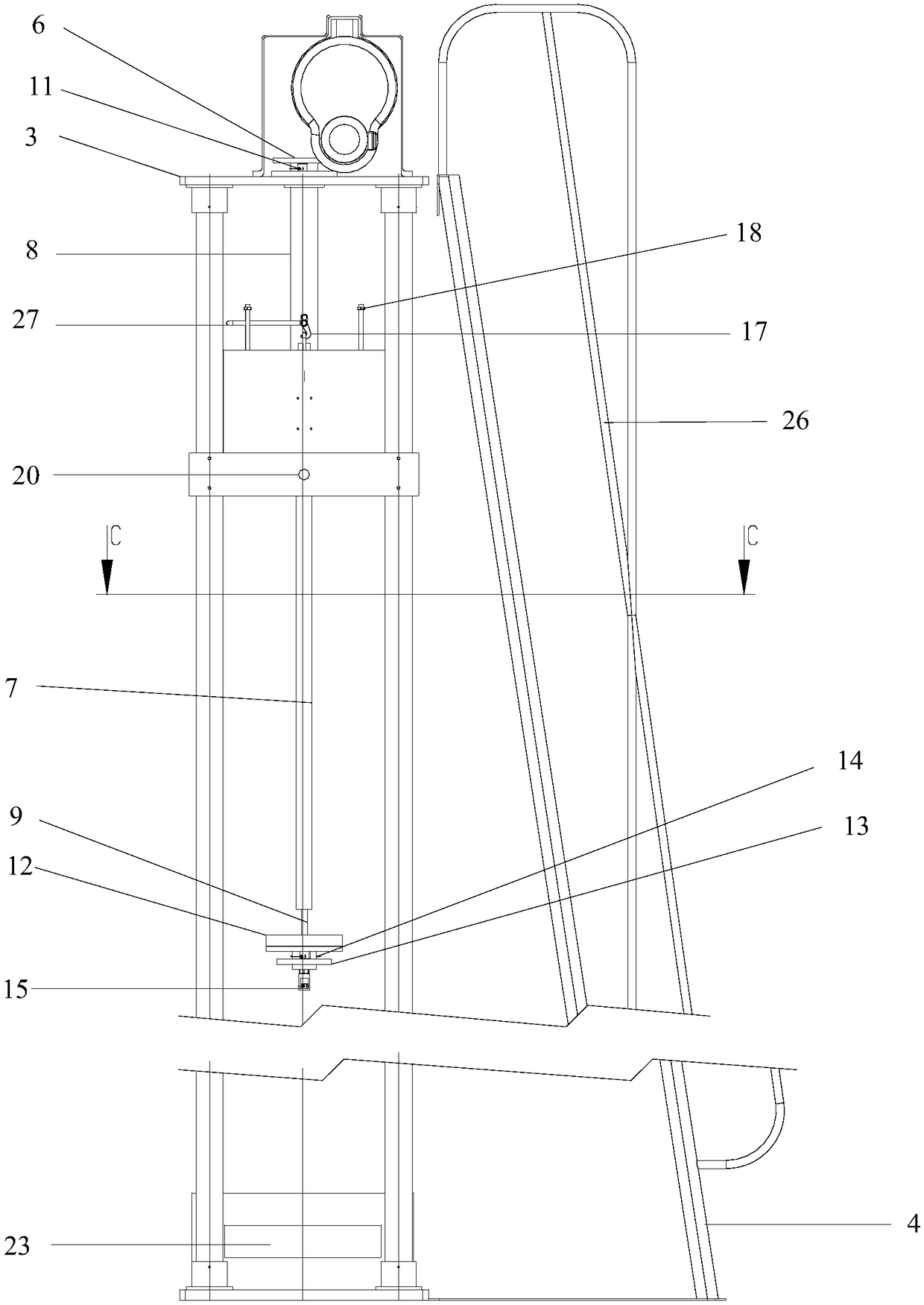
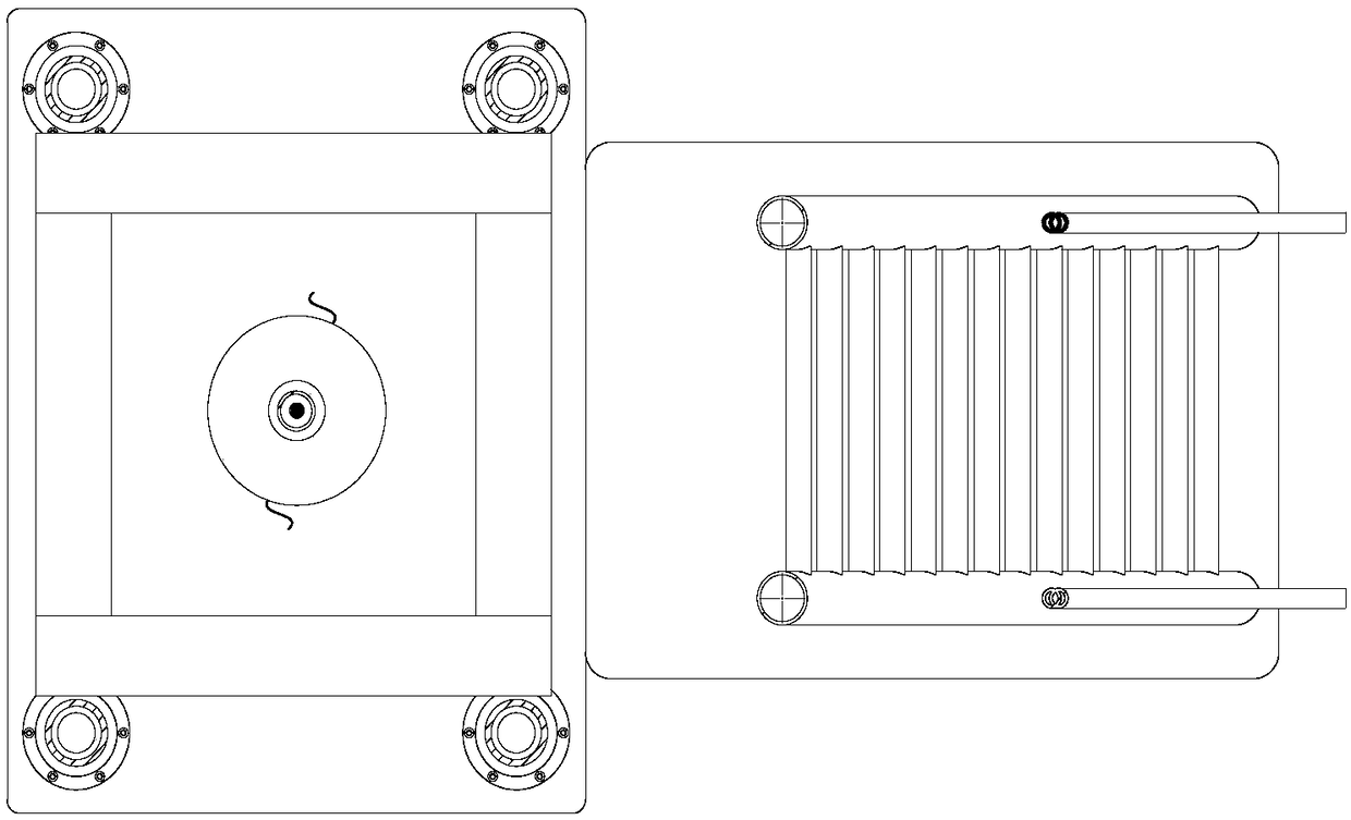
The invention provides a drop hammer type dynamic impact testing machine and a testing method thereof. The testing machine comprises supporting stand columns; a table seat and a fixed platform are respectively arranged at the two ends of the supporting stand columns; a ladder is arranged at one sides of the supporting stand columns; the fixed platform is fixedly provided with a speed reducing motor and a first press plate; a sleeve, a casing and an anchor rod are sequentially arranged at the lower end of the first press plate; the sleeve is connected with a second press plate in a sliding way,and a first pressure sensor is installed on the upper end face of the second press plate; a second pressure sensor is installed on the upper end face of a tray arranged at the lower end of the anchorrod, and a displacement sensor is installed on the lower end face of the tray; a drop hammer also sleeves the casing; an output shaft of the motor is connected with the drop hammer by means of a steel wire rope. The drop hammer type dynamic impact testing machine is novel in structure, high in economic value, economical and convenient to operate, can be used for testing the performance of an energy-releasing anchor rod and a common anchor rod body resisting and absorbing the impact energy under the action of impact load, and can also be used for testing the performance of the energy-releasinganchor rod and the common anchor rod resisting and absorbing the impact energy under the action of the impact load during simulation of on-site anchoring.
Description
Technical field: [0001] The invention relates to a drop hammer dynamic impact testing machine and a test method, in particular to a drop hammer dynamic impact testing machine for testing the dynamic properties of energy-released anchors and other common anchors and rod-type materials, belonging to the impact field of dynamic testing. Background technique: [0002] With the continuous expansion of human demand for resources, shallow resources are increasingly exhausted, and gradually transition to deep resources. Mines at home and abroad have entered the state of deep resource mining one after another. At the same time, with the continuous increase of mining depth, there are more and more engineering disasters, such as mine rock burst, intensified mine pressure, large deformation and rheology of roadway surrounding rock, etc., which pose a huge threat to the safe and efficient mining of deep resources. The roadway stability control problem that is mainly faced in the proces...
Claims
Login to View More Application Information
Patent Timeline
 IPC IPC(8): G01N3/303
CPCG01N3/303G01N2203/0033G01N2203/0075G01N2203/0282G01N2203/0682
Inventor 赵兴东杨晓明李怀宾
Owner NORTHEASTERN UNIV
Features
- Generate Ideas
- Intellectual Property
- Life Sciences
- Materials
- Tech Scout
- Unparalleled Data Quality
- Higher Quality Content
- 60% Fewer Hallucinations
Learn More Browse by: Latest US Patents, China's latest patents, Technical Efficacy Thesaurus, Application Domain, Technology Topic, Popular Technical Reports.
© 2025 PatSnap. All rights reserved.Legal|Privacy policy|Modern Slavery Act Transparency Statement|Sitemap|About US| Contact US: help@patsnap.com