Check patentability & draft patents in minutes with Patsnap Eureka AI!

Combined horizontal bar frame

A horizontal bar frame and combined technology, which is applied to the horizontal bar, sports accessories, muscle training equipment, etc., can solve the problems of poor stability of the horizontal bar frame, easy deformation and breakage of the locking screw, and easy detachment of the locking screw from the column. The effect of firm connection, avoiding looseness and improving stability

Pending Publication Date: 2018-08-14
ZHEJIANG DOSOLY MECHANICAL & ELECTRICAL TECH CO LTD
View PDF1 Cites 2 Cited by
  • Summary
  • Abstract
  • Description
  • Claims
  • Application Information

AI Technical Summary

Problems solved by technology

[0004] Because in the process of use, people hold the horizontal bar with their hands, the horizontal bar is subjected to a vertical downward force, and the locking screw locks the positioning sleeve on the column along the radial direction of the column, the locking screw and the positioning sleeve The contact position is under the stress of pulling down. Long-term use will cause the locking screw to deform and break easily at this part. Since the horizontal bar is straight, people will make the horizontal bar downward at the stress-bearing part when people move on the horizontal bar. Deformation, and then pull the positioning sleeves at both ends of the horizontal bar inward, causing the locking screw to move outward relative to the positioning sleeve, the locking screw is easy to detach from the column, and the stability of the horizontal bar frame is poor; Only the whole horizontal bar frame can be disassembled and stored, which makes the loading, unloading and storage of the horizontal bar frame inconvenient

Method used


Image

  • Combined horizontal bar frame
  • Combined horizontal bar frame
  • Combined horizontal bar frame

Examples


Embodiment Construction

[0033] The following are specific embodiments of the present invention and in conjunction with the accompanying drawings, the technical solutions of the present invention are further described, but the present invention is not limited to these embodiments.

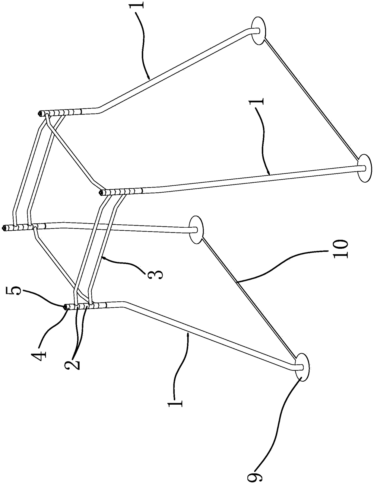
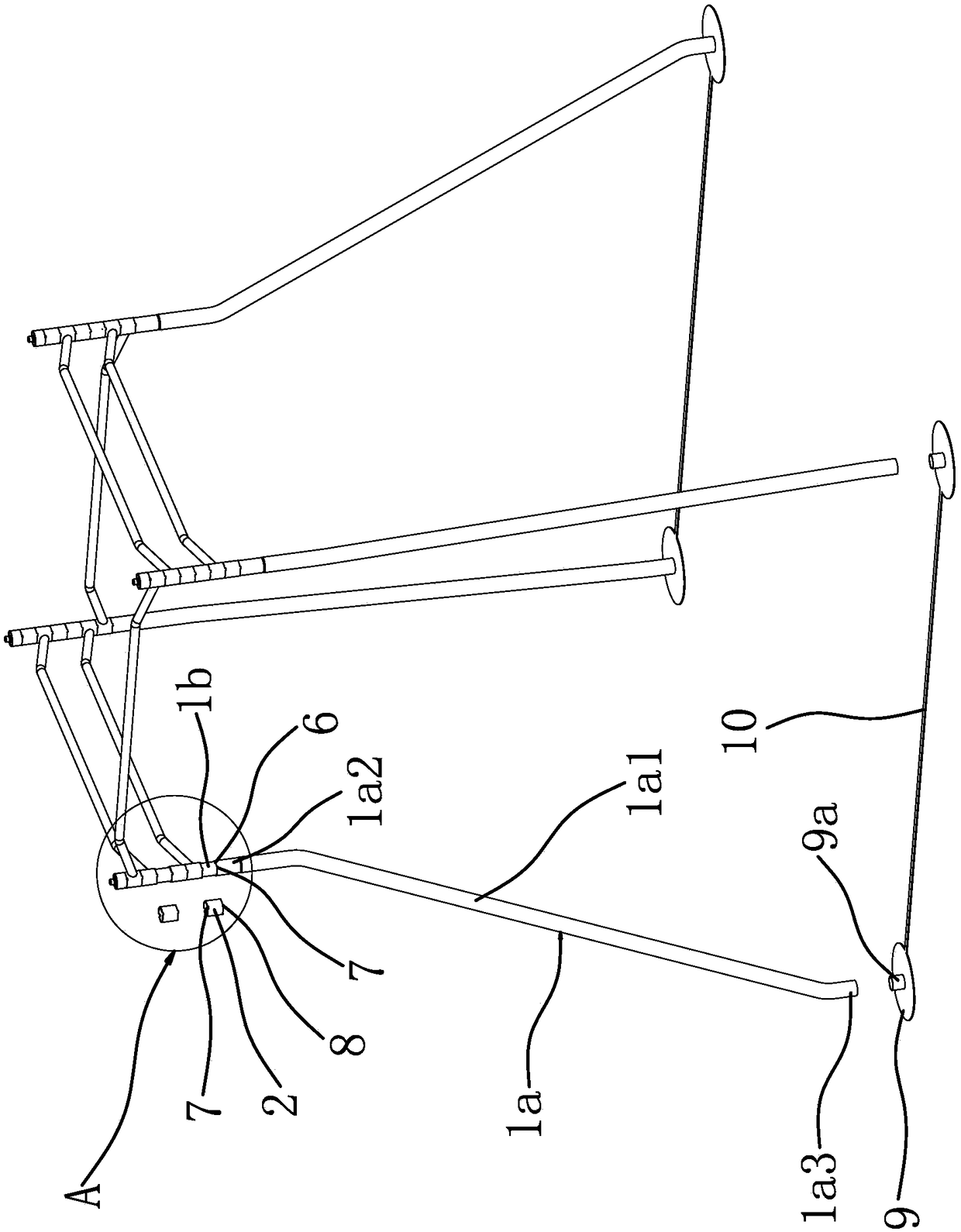
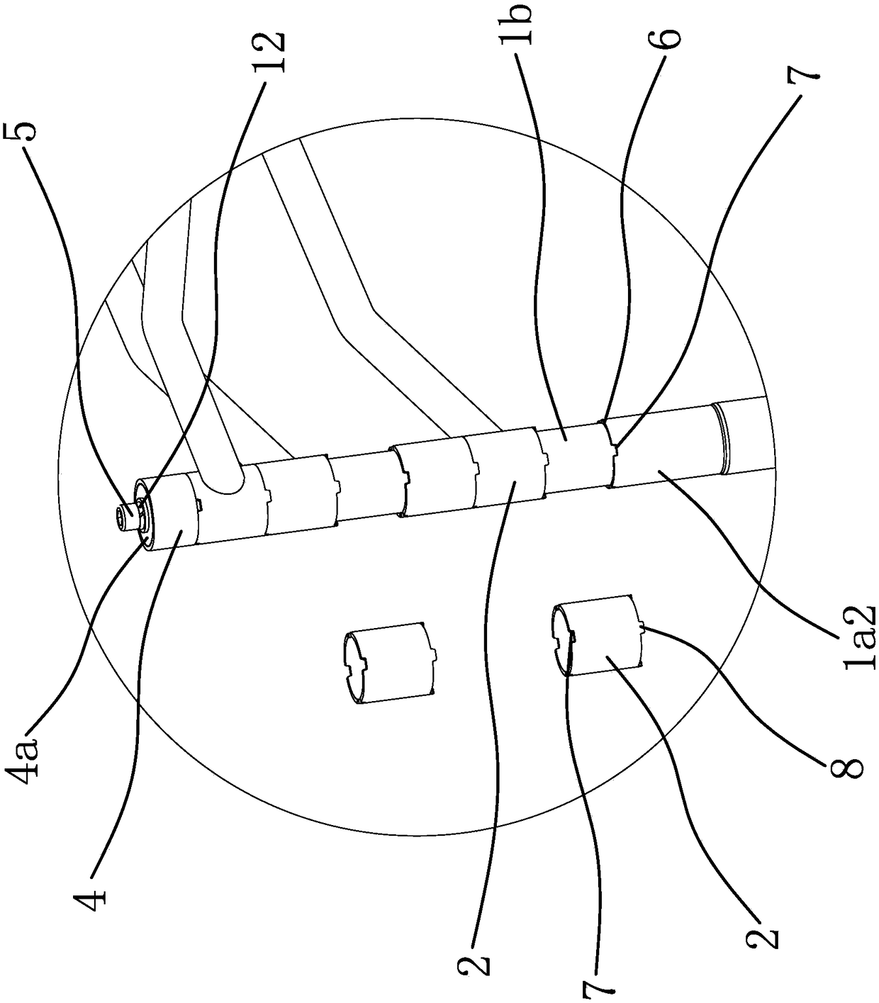
[0034] Such as figure 1 , figure 2 and image 3 As shown, the combined horizontal bar frame includes four support tubes 1 distributed in a rectangular shape. The upper end of each support tube 1 is provided with a positioning sleeve 2, and a horizontal sleeve 2 is provided between two adjacent support tubes 1. Bars 3, the two ends of each horizontal bar 3 are respectively fixed with a positioning sleeve 2 so that each horizontal bar 3 can slide up and down independently along the support tube 1, and the outer peripheral surface of the upper end of the support tube 1 has a support step 6, There are more than two positioning sleeves 2 on each support tube 1 and they are stacked on the support steps 6 in sequence. 4, and ...


PUM


Abstract

The invention provides a combined horizontal bar frame, and belongs to the technical field of exercise equipment. The problems of poor stability and inconvenient storage of existing horizontal bars are solved. The combined horizontal bar frame comprises four supporting tubes which are distributed as a matrix, the upper end part of each supporting tube is sleeved with a positioning sleeve, cross bars are arranged between the adjacent two supporting tubes, each of the two ends of each cross bar is fixedly connected with a positioning sleeve, supporting steps are arranged on the outer circumferences of the upper end parts of the supporting tubes, two or more positioning sleeves are arranged on each supporting tube and sequentially overlapped on the supporting steps, the upper ends of the supporting tubes are sleeved with limiting locking sleeves used for pressing the positioning sleeves tightly, the limiting locking sleeves are locked on the supporting tubes through fastening members which are in threaded connection with the supporting tubes, and the fastening members are arranged in the vertical directions and penetrate through the limiting locking sleeves. According to the combinedhorizontal bar frame, the stability of the horizontal bar frame can be improved which the folding of the horizontal frame is convenient.

Description

technical field [0001] The invention belongs to the technical field of sports equipment and relates to a combined horizontal bar frame. Background technique [0002] With the continuous development of science and technology, people pay more and more attention to physical exercise. However, due to various reasons, most people do not want or want to go out of the gym to exercise, but prefer to buy fitness equipment and exercise directly at home. . [0003] And the existing horizontal bar frame belongs to relatively common fitness equipment, when the horizontal bar frame is installed indoors, because the height of the people who use it is different, it is often necessary to adjust the height of the horizontal bar. hole, by inserting the horizontal bar in the hole of the corresponding height, and fixing the horizontal bar on the installation pipe by bolts, such as a Chinese patent application (patent application number: 201420167172.3) discloses an adjustable four-sided horizon...

Claims


Application Information

Patent Timeline
Patent Type & Authority Applications(China)
IPC IPC(8): A63B1/00A63B17/04
CPCA63B1/00A63B17/04A63B2210/50A63B21/068A63B23/12A63B23/1218A63B2225/093
Inventor 单才华郭政徐高杨尹如中梁日新范英
Owner ZHEJIANG DOSOLY MECHANICAL & ELECTRICAL TECH CO LTD
Features
  • R&D
  • Intellectual Property
  • Life Sciences
  • Materials
  • Tech Scout
  • Unparalleled Data Quality
  • Higher Quality Content
  • 60% Fewer Hallucinations
Learn More