A kind of automatic lifting type stamping die

A stamping die, automatic technology, applied in the direction of forming tools, metal processing equipment, manufacturing tools, etc., can solve the problems of poor matching effect of a single arc hook plate, easy to be pressed by the mold, etc.

Active Publication Date: 2020-10-23
SUZHOU RIPU MOLD CO LTD
View PDF6 Cites 0 Cited by
  • Summary
  • Abstract
  • Description
  • Claims
  • Application Information

AI Technical Summary

Problems solved by technology

[0003] The main technical problem to be solved by the present invention is to provide an automatic feeding stamping die, which solves the problem that sheet-shaped workpieces are difficult to take out on the stamping die, and the single arc-shaped hook plate has poor matching effect and is easily pressed by the die.

Method used


Image

  • A kind of automatic lifting type stamping die
  • A kind of automatic lifting type stamping die
  • A kind of automatic lifting type stamping die

Examples


Embodiment Construction

[0012] The preferred embodiments of the present invention will be described in detail below in conjunction with the accompanying drawings, so that the advantages and features of the present invention can be more easily understood by those skilled in the art, so as to define the protection scope of the present invention more clearly.

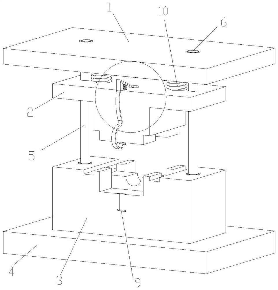
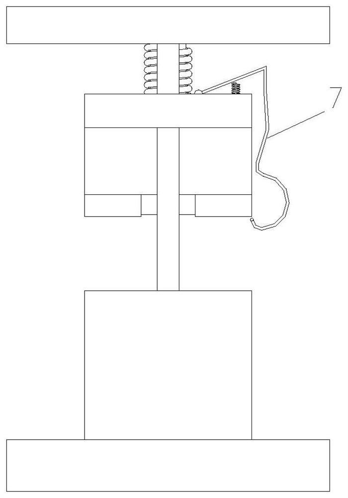
[0013] Please refer to the attached Figures 1 to 3 , the embodiment of the present invention includes:

[0014] An automatic lifting type stamping die includes a top plate 1, an upper die 2, a lower die 3, a bottom plate 4 and an arc-shaped hook plate 7. The lower mold 3 is fixed on the bottom plate 4, and the upper mold 2 is connected with the top plate 1. The lower die 3 is provided with a mounting hole; the mounting hole is provided with a guide post 5 for lifting and guiding the upper die. . Two guide posts 5 are provided, and the two guide posts 5 are fitted on the upper mold 2 through guide sleeves. The lower die 3 is provided with a p...


PUM


Abstract

The invention discloses an automatic lifting type stamping die which comprises a top plate, an upper die, a lower die, a bottom plate and an arc hook plate. The lower die is fixed to the bottom plate,the upper die is connected with the top plate, a supporting spring is arranged between the upper die and the top plate, the upper die is further provided with the arc hook plate for lifting, the archook plate is provided with an arc area which is restored in the die direction, the upper end of the arc hook plate is fixed to the top face of the upper die though a rotating shaft, a telescopic spring is arranged between the upper end of the arc hook plate and the top face of the upper die, the telescopic spring supports the upper end of the arc hook plate to enable the lower end of the arc hookplate to produce no pressure, the lower end of the arc hook plate is a hooking end, the hooking end is lower than the bottom face of the upper die, the hooking end is a circular arc bent upwards in the die direction, the end of the hooking end is provided with a columnar rubber head, the side face of the lower die is provided with an I-shaped groove matched with the arc hook plate, the I-shaped groove extends to the bottom face inside a machining area, and the rubber head is clamped into the I-shaped groove and slides out of the opening of the I-shaped groove from the bottom face inside the machining area.

Description

technical field [0001] The invention relates to the field of mold structure, in particular to an automatic lifting type stamping die. Background technique [0002] At present, in the process of cold stamping blanking on the stamping die, since the general blanking is blanking without waste around, the material is usually returned by the action of the unloading plate on the lower die, so that the edge of the material can lift the blank Remove from the lower mold, and then manually shake the steel plate to collect the blanks. This purely manual picking method is time-consuming, labor-intensive, and the production cycle is slow. In addition, if the production method of cutting off the edge of the material as waste is punched, it will bring a lot of inconvenience to take the material. Contents of the invention [0003] The technical problem mainly solved by the present invention is to provide an automatic feeding stamping die, which solves the problem that on the stamping die...

Claims


Application Information

Patent Timeline
Patent Type & Authority Patents(China)
IPC IPC(8): B21D37/10B21D45/04
CPCB21D37/10B21D45/04
Inventor 刘曾
Owner SUZHOU RIPU MOLD CO LTD
Why Eureka
Try Eureka