Bionic fish system based on series-parallel pneumatic muscles

A technology of pneumatic muscles and bionic fish, which is applied in the field of bionic robots, can solve the problems of limited movement space, lack of flexibility, and inability to simulate muscle distribution, etc., and achieve the effect of compact structure, good flexibility, and high power/mass ratio

Inactive Publication Date: 2018-08-14
JIAXING UNIV
View PDF15 Cites 3 Cited by
  • Summary
  • Abstract
  • Description
  • Claims
  • Application Information

AI Technical Summary

Problems solved by technology

[0002] The fish swim in the water, which is mainly completed by the muscles driving the fish spine to drive the tail to swing. In order to understand the influencing factors of fish swimming and the role of muscles in fish swimming, Chinese patents 201610718523.9 and 201610717838.1 adopt the design of eccentric wheel and rod mechanism For bionic fish, Chinese patents 201410358254.0, 201610682541.6, 201710232618.4, and 201611224006.2 use motors in series to drive and release raw fish. All of the above are components composed of rigid components and do not have flexibility
Pneumatic muscles have good flexibility. Chinese patent 201610398696.7 uses multiple pneumatic muscles in parallel to form a parallel mechanism as a single joint for releasing fish, and then connects multiple pneumatic muscles in parallel, which cannot simulate the actual muscle distribution of fish. Chinese patent 20171035116.X uses pneumatic muscles to drive the rope to design the bionic fish. It only simulates the distribution of the tail muscles. The stiffness of each joint cannot be adjusted randomly, and its movement space is limited by the actual contraction of the pneumatic muscles.

Method used


Image

  • Bionic fish system based on series-parallel pneumatic muscles
  • Bionic fish system based on series-parallel pneumatic muscles
  • Bionic fish system based on series-parallel pneumatic muscles

Examples


Embodiment Construction

[0024] The present invention will be described in detail below according to the accompanying drawings and preferred embodiments, and the purpose and effect of the present invention will become clearer. The present invention will be further described in detail below in conjunction with the accompanying drawings and embodiments. It should be understood that the specific embodiments described here are only used to explain the present invention, not to limit the present invention.

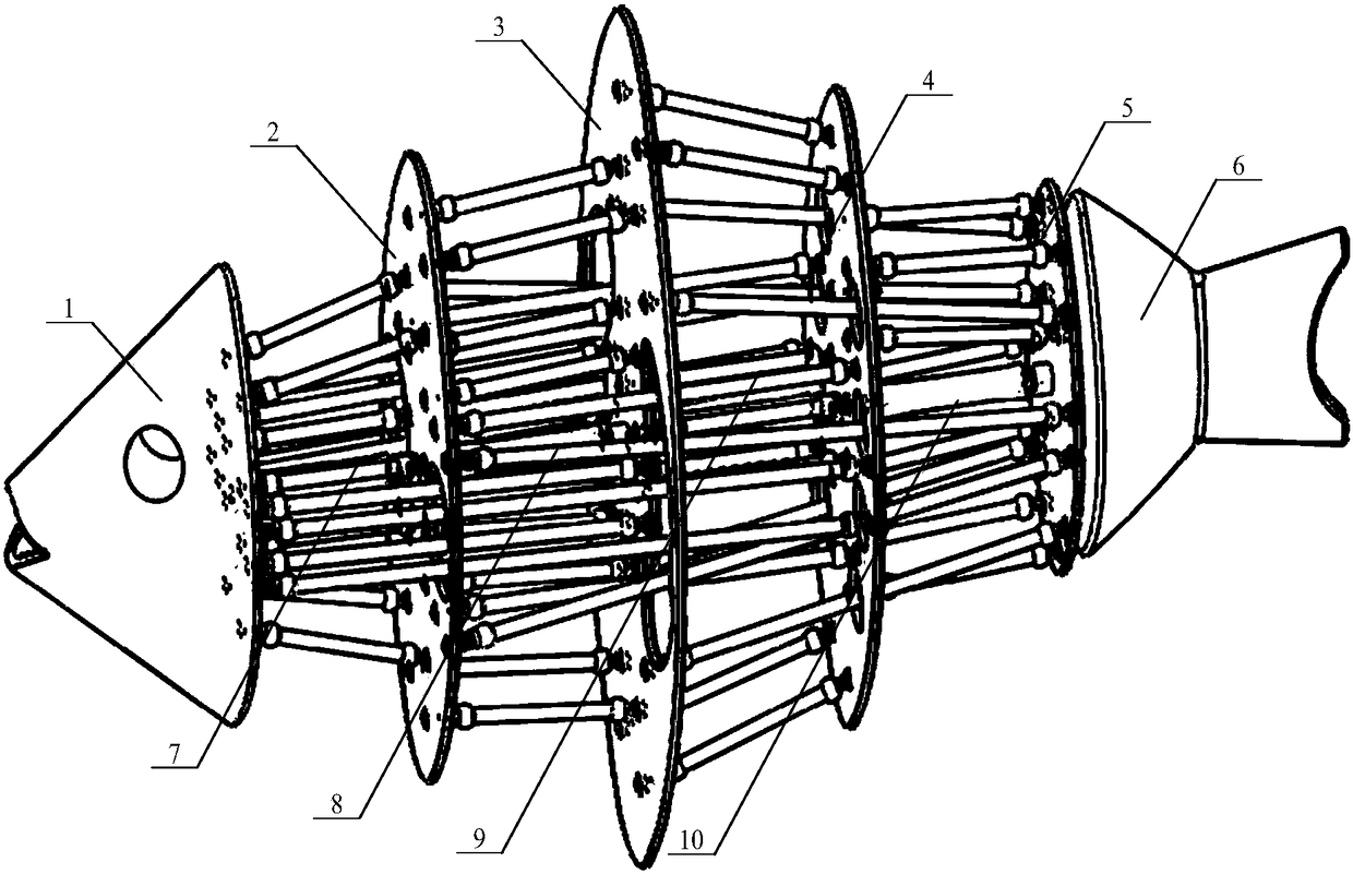
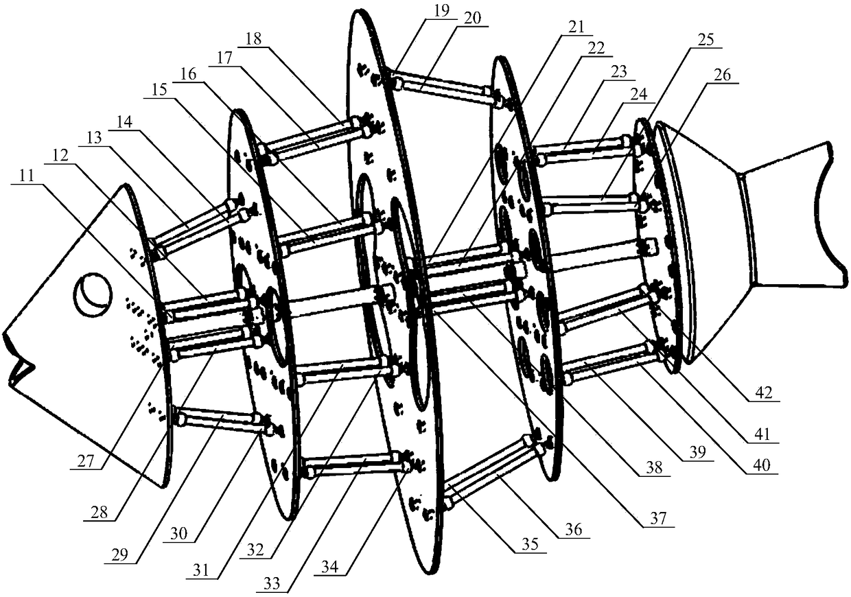
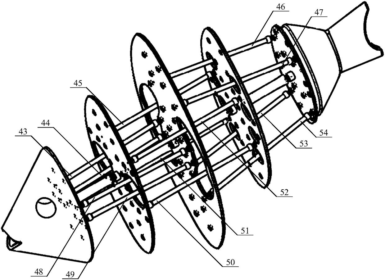
[0025] Take n=4 as an example, specifically as Figure 1-4 As shown, a bionic fish system based on a hybrid pneumatic muscle of the present invention includes: a fish head 1, a first layer of pneumatic muscle connecting plate 2, a second layer of pneumatic muscle connecting plate 3, a third layer of pneumatic muscle connecting plate 4, The fourth layer of pneumatic muscle connecting plate 5, tail fin 6, spine 1 7, spine 2 8, spine 3 9, spine 4 10, first layer of pneumatic muscle 11, first layer of pneu...


PUM


Abstract

The invention discloses a bionic fish system based on series-parallel pneumatic muscles. According to the bionic fish system, muscles of a fish are simulated by the pneumatic muscles to drive the motion of a multi-joint fish, and the function of completely simulating the motion of the fish can be achieved. The bionic fish comprises a fish head, pneumatic muscle connecting plates, a tail fin, spines, a single-joint pneumatic muscle, a two-joint pneumatic muscle, a three-joint pneumatic muscle, and an n-1-joint pneumatic muscle; the fish head is connected to the spines in a rotating mode, and the pneumatic muscle connecting plates are connected to the spines in a rotating mode; the two ends of the pneumatic muscles are connected to the pneumatic muscle connecting plates in a rotating mode; the single-joint pneumatic muscle, the two-joint pneumatic muscle, the three-joint pneumatic muscle, and the n-1-joint pneumatic muscle are correspondingly and simultaneously connected to a single joint, two joints, three joints, and n-1 joints; and the pneumatic muscles are controlled to be inflated and deflated according to actual needs, so that the fish can swim at different speeds. The bionic fish system is driven through the pneumatic muscles and has the advantages of being compact in structure, clean, good in anti-explosion performance and capable of being used for underwater and water surface operation, teaching demonstration and scientific research.

Description

technical field [0001] The invention belongs to the technical field of bionic robots, and in particular relates to a bionic fish system based on hybrid pneumatic muscles. Background technique [0002] The fish swim in the water, which is mainly completed by the muscles driving the fish spine to drive the tail to swing. In order to understand the influencing factors of fish swimming and the role of muscles in fish swimming, Chinese patents 201610718523.9 and 201610717838.1 adopt the design of eccentric wheel and rod mechanism For bionic fish, Chinese patents 201410358254.0, 201610682541.6, 201710232618.4, and 201611224006.2 use motors in series to drive and release raw fish. All of the above are components composed of rigid components and do not have flexibility. Pneumatic muscles have good flexibility. Chinese patent 201610398696.7 uses multiple pneumatic muscles in parallel to form a parallel mechanism as a single joint for releasing fish, and then connects multiple pneumat...

Claims


Application Information

Patent Timeline
Patent Type & Authority Applications(China)
IPC IPC(8): B25J9/00B25J9/10B25J9/14B25J17/00B63H1/36
CPCB25J9/0072B25J9/1075B25J9/14B25J17/00B63H1/36
Inventor 姜飞龙朱荷蕾殷小亮宋玉来钱承刘睿莹杨立娜张海军朱海滨
Owner JIAXING UNIV
Why Eureka
Try Eureka