Robot based on rigid and flexible pneumatic element fusion, control system and control method

A pneumatic component and control system technology, applied in the field of robotics, can solve problems such as the limitation of movement space and freedom of movement, change of joint friction coefficient, unfavorable joint servo control, etc., and achieve the effect of compact structure, increased degree of freedom, and increased quantity

Inactive Publication Date: 2022-05-10
YUNNAN COLLEGE OF BUSINESS MANAGEMENT
View PDF10 Cites 0 Cited by
  • Summary
  • Abstract
  • Description
  • Claims
  • Application Information

AI Technical Summary

Problems solved by technology

[0004] Chinese patents CN110561457A, CN107283413A, CN107550688A, and CN108466256A respectively propose a pneumatic robot that uses ball joints to connect the joints and uses pneumatic muscles or pneumatic muscles to drive the joints to rotate; however, the range of motion of these robots can only rotate, and the space and freedom of motion are limited Great limitations; these robots are in a complex working environment, the collision is inevitable, it is bound to cause damage to the spherical joint of the joint, change the friction coefficient of the joint, and even change the friction force, which is extremely unfavorable to the servo control of the joint

Method used


Image

  • Robot based on rigid and flexible pneumatic element fusion, control system and control method
  • Robot based on rigid and flexible pneumatic element fusion, control system and control method
  • Robot based on rigid and flexible pneumatic element fusion, control system and control method

Examples


Embodiment 1

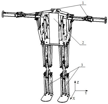
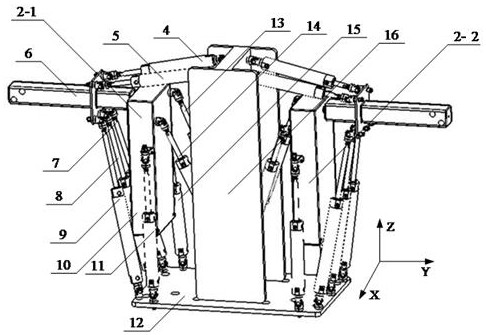
[0034] Example 1: as figure 1 ,2 , 3, 4, 5, and 6, the robot based on the fusion of rigid and flexible pneumatic components includes a double upper limb system 1, a thoracic joint system 2, and a double lower limb system 3. The thoracic joint system 2 includes the middle bone 16 and is located around the middle bone 16. The left thoracic joint 2-1 and the right thoracic joint 2-2 on both sides, and the structure of the left thoracic joint 2-1 and the right thoracic joint 2-2 are exactly the same. The double lower limb system 3 includes a left lower limb 3-1 and a right lower limb 3-2, and the structure of the left lower limb 3-1 and the right lower limb 3-2 is exactly the same.

[0035] like figure 2 , 3 As shown, the middle bone 16 is fixedly connected with the lower bottom plate 12 . Cylinder six 11, cylinder nine 15 two ends are rotatably connected with side bone 10, lower base plate 12 respectively, and cylinder six 11 is on the front side, cylinder nine 15 is on the r...


PUM


Abstract

The invention discloses a robot based on rigid and flexible pneumatic element fusion, a control system and a control method, and belongs to the technical field of robots. The robot is mainly composed of an air cylinder, pneumatic muscles, a lower bottom plate, side bones, middle bones, connecting rods, thigh side panels, shank side panels, pneumatic motors and a control system. The multiple air cylinders drive the chest joints to linearly move and rotate, and the multiple air cylinders of the shoulder joints drive the joints to rotate and assist the chest joints to move at the same time. The elbow joint is formed by combining a thin-wall air cylinder and two sets of four-bar mechanisms. The hip joints and the ankle joints are driven by multiple groups of pneumatic muscles on the outer sides and connected by one or more pneumatic muscles in the middle, so that the hip joints and the ankle joints can assist in driving and can also play a role of spherical hinges, and the knee joints are synergistically moved by two pneumatic muscles. The mechanical arm is driven by the pneumatic muscle and the air cylinder, has the characteristics of rigidity and flexibility, multiple degrees of freedom and large working space, and can be used for commercial services such as teaching demonstration, industrial automatic production lines, catering and ordering and the like.

Description

technical field [0001] The invention relates to a robot, a control system and a control method based on fusion of rigid and flexible pneumatic components, and belongs to the technical field of robots. Background technique [0002] Pneumatic technology is clean, and air has the advantage of being inexhaustible. At the same time, pneumatic has the advantage of low cost compared with hydraulic pressure, and it is widely used in industrial automation production lines. [0003] Pneumatic components mainly include rigid component cylinder and flexible component pneumatic muscle; the cylinder can provide both pulling force and pushing force, while the pneumatic muscle can only provide pulling force, but the pneumatic muscle can provide supporting force after inflation, which is equivalent to a cylinder with a certain stiffness . If multiple pneumatic muscles cooperate to provide pulling force, the effect of pushing can be achieved. [0004] Chinese patents CN110561457A, CN1072834...

Claims


Application Information

Patent Timeline
Patent Type & Authority Applications(China)
IPC IPC(8): B25J11/00B62D57/032B25J9/14B25J17/02B25J9/16
CPCB25J11/00B62D57/032B25J9/14B25J17/02B25J17/0283B25J9/161
Inventor 李庆伟
Owner YUNNAN COLLEGE OF BUSINESS MANAGEMENT
Why Eureka
Try Eureka