Fracture fixing frame

A fixation frame and fixation hole technology, applied in fractures, medical science, etc., can solve problems such as unsmooth recovery, heat sores, and affecting surgical results, so as to prevent common complications in orthopedics, promote fracture healing, and relieve heat accumulation. Effect

Inactive Publication Date: 2018-08-17
梁钰婕
View PDF0 Cites 0 Cited by
  • Summary
  • Abstract
  • Description
  • Claims
  • Application Information

AI Technical Summary

Problems solved by technology

[0002] In recent years, with the development of the transportation industry and the construction industry, the annual incidence of fractures is on the rise, and surgery is currently the most effective treatment method. Postoperative recovery requires stability and improvement of compressed nerves. Function; For patients with lower limb orthopedic injuries, regardless of whether the skeletal joint, thigh, knee joint, or calf have been operated on, it is necessary to maintain a moderate stepping joint abduction neutral position to prevent fracture displacement, fat nerve compression, foot drop and Joint stiffness affects the effect of surgery and cannot recover smoothly
In the prior art, such patients cannot automatically maintain this position for a long time after surgery, and the fixed ankle binding is likely to cause bedsores or heat sores at the binding site in summer, which is not conducive to the recovery of patients

Method used


Image

  • Fracture fixing frame

Examples


Embodiment Construction

[0011] The technical solution of this patent will be further described in detail below in conjunction with specific embodiments.

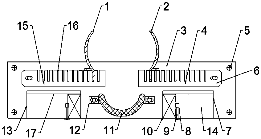
[0012] see figure 1 , a fracture fixation frame, comprising a fixed base plate 3, an arc-shaped bottom bracket 11, a left slot plate 15, a right slot plate 6, a left guard frame 1, a right guard frame 2, a slot 16, a left radiator 13 and a right radiator device 7; wherein said fixed bottom plate is provided with fixing parts 5 around; said fixing parts 5 positioning pins or locking bolts; upper and lower two-layer fixing holes are arranged on the fixing bottom plate 3, and pass through the upper fixing holes The adjusting bolt 12 is fixedly equipped with a left slot plate 15 and a right slot plate 6, and the left slot plate 15 and the right slot plate 6 can move left and right along the horizontal direction through the fixing holes, thereby adjusting the distance between them; The lower fixing hole is fixedly equipped with an arc-shaped bottom bra...


PUM


Abstract

The invention discloses a fracture fixing frame. The fracture fixing frame comprises a fixing bottom plate, an arc bottom support, a left inserting groove plate, a right inserting plate, a left guardframe, a right guard frame, inserting grooves, a left radiator and a right radiator; fixing members are arranged around the fixing bottom plate; the fixing members are positioning pins or locking bolts; upper fixing holes and lower two fixing holes are formed in the fixing bottom plate; the left inserting groove plate and the right inserting groove plate are fixedly arranged in the upper fixing holes through adjustment bolts; the adjustment bolts moves with the lower fixing holes through threaded holes so as to change a horizontal position of the arc bottom support; the right end of the left inserting groove plate is placed on an upper left side of the arc bottom support, and the left end of the right inserting groove plate is placed on an upper right side of the arc bottom support; the left radiator and the right radiator are arranged on the left side and the right side of the arc bottom support respectively; a plurality of inserting grooves are formed in the upper parts of the left inserting groove plate and the right inserting groove plate; and the left guard frame is inserted into and fixed on the inserting grooves formed in the left inserting groove plate, and the right guideframe is inserted into and fixed on the inserting grooves formed in the right inserting groove plate.

Description

technical field [0001] The invention relates to the field of medical devices, in particular to a fracture fixation frame. Background technique [0002] In recent years, with the development of the transportation industry and the construction industry, the annual incidence of fractures has been on the rise, and surgery is currently the most effective treatment method. Postoperative recovery requires stability and improvement of compressed nerves. Function: For patients with lower limb orthopedic injuries, regardless of whether the skeletal joints, thighs, knee joints, or calves have been operated on, it is necessary to maintain a moderate neutral position of stepping on the joint abduction to prevent displacement of fracture ends, compression of fat nerves, foot drop and The joint is stiff, which affects the effect of the operation and cannot recover smoothly. In the prior art, such patients cannot automatically maintain this position for a long time after surgery, and fixed...

Claims


Application Information

Patent Timeline
IPC IPC(8): A61F5/05
CPCA61F5/05
Inventor 梁钰婕
Owner 梁钰婕
Why Eureka
Try Eureka