Hearth soot blower

A technology of soot blowing device and furnace, which is applied in the direction of lighting and heating equipment, etc. It can solve the problems of poor combustion stability, dead angle of soot blowing in the furnace, and decrease of boiler output, so as to achieve less medium loss, eliminate dead angle of soot blowing, and relieve heat. Alluvial effect

Inactive Publication Date: 2010-12-22
NANJING UNIV OF SCI & TECH
View PDF6 Cites 5 Cited by
  • Summary
  • Abstract
  • Description
  • Claims
  • Application Information

AI Technical Summary

Problems solved by technology

[0007] The purpose of the present invention is to provide a furnace soot blowing device, which is used to solve the problems of poor combustion stability and boiler output drop during the furnace soot blowing period, and also to solve the problem of furnace soot blowing dead angle

Method used


Image

  • Hearth soot blower
  • Hearth soot blower
  • Hearth soot blower

Examples


Embodiment Construction

[0014] The present invention will be described in further detail below in conjunction with the accompanying drawings.

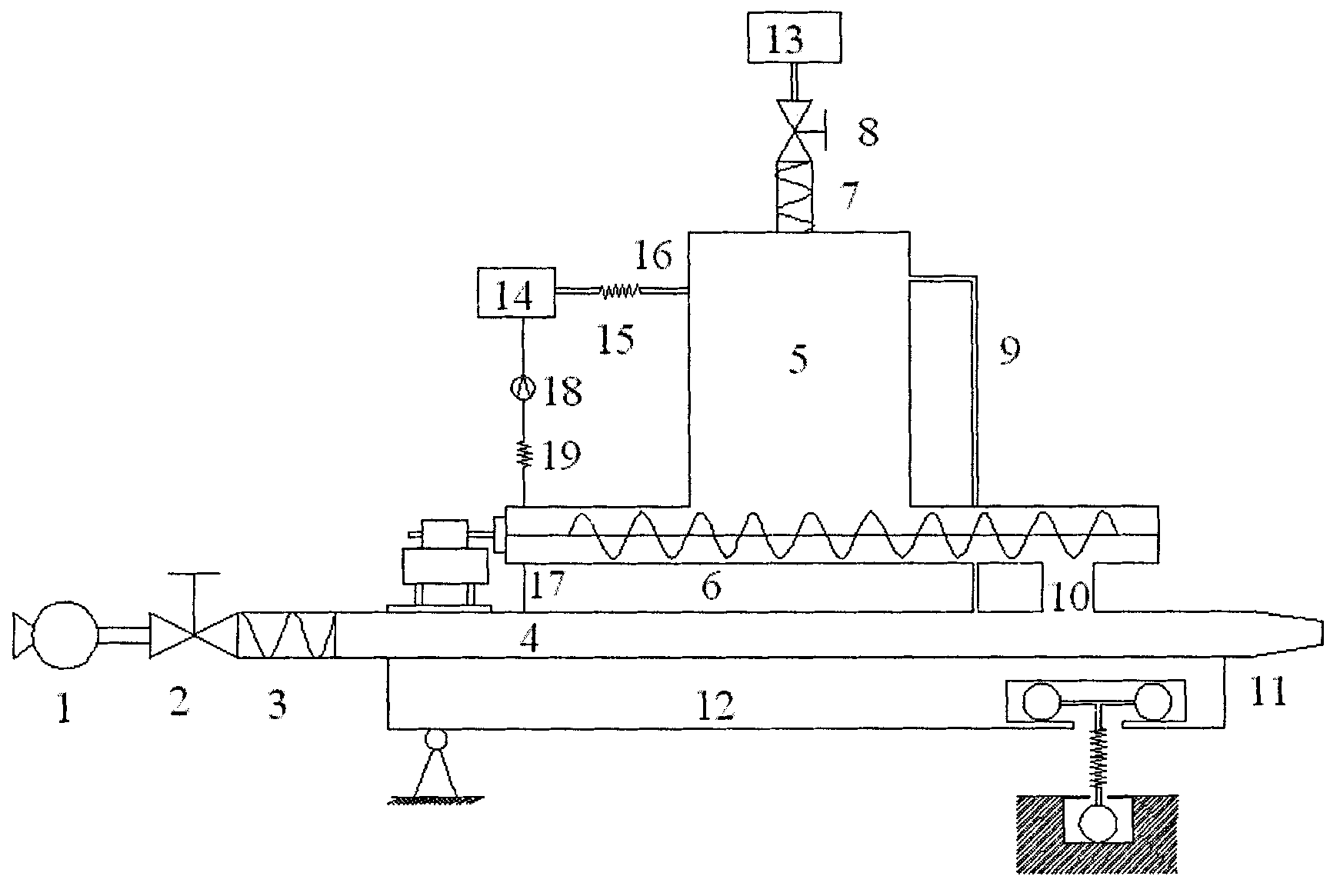
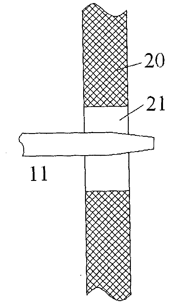
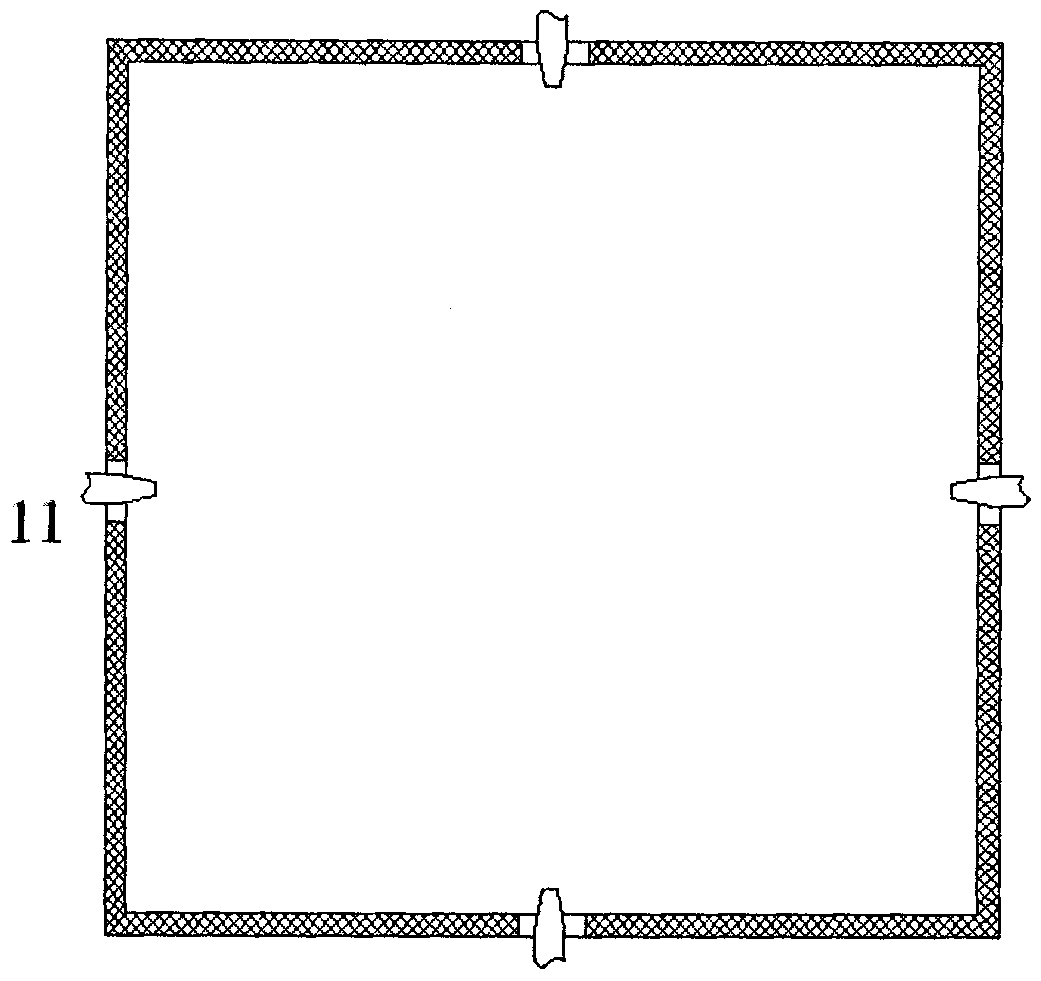
[0015] figure 1 It is a structural schematic diagram of the furnace soot blowing device of the present invention. The furnace soot blowing device of the present invention mainly includes a Roots blower 1, an air volume regulating valve 2, a hose 3 in front of the launching tube, a launching air duct 4, an ice bin 5, and a screw conveyor 6 , ice bin inlet hose 7, ice bin inlet valve 8, pressure balance pipe 9, discharge port 10, nozzle 11, scanning platform 12, ice pill machine 13, air cooler 14, cold air supply hose 15, cold air inlet pipe 16. Cold air outlet pipe 17, circulating fan 18, cold air return hose 19; launch air duct 4, ice bin 5, screw conveyor 6, pressure balance pipe 9, and discharge port 10 adopt double-layer wall structure, the outer wall and inner wall There is a cold air channel between them, see figure 2 , Roots blower 1, air volume cont...


PUM


Abstract

The invention discloses a hearth soot blower which is composed of a Roots blower, a volume regulating valve, a transmitting tube front hose, a transmitting duct, an ice bunker, a spiral conveyer, a scanning platform, an ice pellet machine, an air cooler, a cold air hose, a cold air inlet pipe, a cold air outlet pipe, a recirculating blower, a cold air return hose and the like, wherein the Roots blower pressurizes air into the transmitting duct; the prefabricated ice pellets are filled into the ice bunker; the ice pellets are continuously and quantitatively added into the transmitting duct through the spiral conveyer and a blanking port so as to form the air-particle two-phase mixture; the mixture accelerates at the jet port to form a high-speed jetted ice pellet particle group; and the high-speed jetted ice pellet particle group is transmitted into the hearth and impacts the opposite hearth soot deposit wall surface to realize the soot blowing operation after short-time flying. The invention uses high speed ice pellets to realize soot blowing, has the advantages of low mass of soot blowing medium and favorable soot blowing effect, can greatly relieve the problems of thermal shock, load, efficiency and the like, basically eliminates dead spaces of soot blowing, is convenient to install and operate, and is applicable to hearth soot blowing (deslagging) of a station boiler.

Description

technical field [0001] The invention relates to a furnace soot blowing device, in particular to a furnace soot blowing device using ice pellets as a soot blowing medium. Background technique [0002] The impact of furnace slagging on the operation of power plant boilers is mainly manifested in the fact that the slag layer covers the heating surface, reduces the heat absorption of the furnace, and causes the flue gas temperature at the furnace outlet to rise, and the increase in the flue gas temperature at the furnace outlet and the development of slagging promote each other This positive feedback mechanism shows that once the furnace slagging exceeds a certain limit without timely intervention, the slagging process may go out of control and develop indefinitely, and a series of changes will occur in the operating parameters of the furnace, including the flue gas temperature at the furnace outlet. Gradually rising, the nitrogen oxide content in the flue gas gradually increase...

Claims


Application Information

Patent Timeline
Patent Type & Authority Applications(China)
IPC IPC(8): F23J1/00
Inventor 刘心志熊荣辉朱曙光张后雷
Owner NANJING UNIV OF SCI & TECH
Why Eureka
Try Eureka